Alternator Wiring Diagram With Voltage Regulator
For the seasoned DIYer, understanding your vehicle's charging system is crucial for everything from routine maintenance to complex modifications. The alternator wiring diagram, particularly in conjunction with the voltage regulator, is the key to unlocking this knowledge. This article will provide an in-depth look at these diagrams, enabling you to diagnose issues, perform repairs, and even plan aftermarket upgrades with confidence.
Why This Diagram Matters
Imagine your car battery suddenly dying while you're miles from home. Knowing how to read an alternator wiring diagram empowers you to troubleshoot the charging system, potentially identifying a faulty wire, a failing alternator, or a problematic voltage regulator. It's not just about fixing problems; it's about understanding the flow of electricity and how the various components interact. Furthermore, if you are planning to install a high-powered audio system or other electrical accessories, comprehending the diagram is essential for ensuring your charging system can handle the increased load, and upgrading if necessary. It also comes in handy when performing engine swaps or modifying the vehicle's electrical system.
Key Specs and Main Parts
Before diving into the diagram itself, let's define the core components and their roles:
- Alternator: The heart of the charging system. It converts mechanical energy from the engine (via a belt) into electrical energy (AC), which is then rectified into DC current suitable for charging the battery and powering the vehicle's electrical system. Its output is typically measured in Amperes (Amps or A). Most alternators output between 60A and 150A depending on the vehicle.
- Voltage Regulator: This crucial component maintains a stable voltage output from the alternator, typically around 13.8V to 14.4V. Without it, the alternator's output voltage would fluctuate wildly with engine speed, potentially damaging sensitive electronic components and overcharging the battery. Some voltage regulators are integrated into the alternator, while others are external.
- Battery: Acts as a reservoir for electrical energy, providing power to start the engine and supplementing the alternator's output when demand is high. Battery capacity is measured in Amp-hours (Ah).
- Wiring Harness: The network of wires connecting all electrical components. Wires are often color-coded for easy identification (more on this later).
- Fuses and Relays: Protection devices that prevent damage from overloads and control high-current circuits, respectively.
- Ignition Switch: Controls the flow of power to the alternator's field winding, enabling the charging process.
Diagram Symbols: Deciphering the Code
Understanding the symbols used in the wiring diagram is paramount. Here's a breakdown of common elements:
- Lines: Represent wires. Thicker lines typically indicate wires carrying higher current.
- Colors: Wires are often color-coded (e.g., red for power, black for ground). The legend on the diagram will explain the color scheme. Be aware that color codes can vary between manufacturers.
- Connectors: Represented by circles, squares, or other shapes indicating where wires are joined.
- Ground: Usually depicted as a series of descending lines or a triangle, indicating a connection to the vehicle's chassis (ground).
- Alternator Symbol: Varies, but often a circle with a wavy line inside, sometimes labeled "ALT."
- Voltage Regulator Symbol: Another box or rectangle shape with 'VR' or 'REG' inside.
- Battery Symbol: Represented by one long and one short parallel line, indicating the battery's positive and negative terminals, respectively. The positive terminal is the longer one.
- Fuse Symbol: A squiggly line inside a rectangle, indicating a fuse.
- Relay Symbol: A coil and a switch, representing the relay's electromagnetic coil and the contacts it controls.
Important: Always refer to the specific wiring diagram for your vehicle make, model, and year, as symbols and wiring configurations can vary.
How It Works: The Charging System in Action
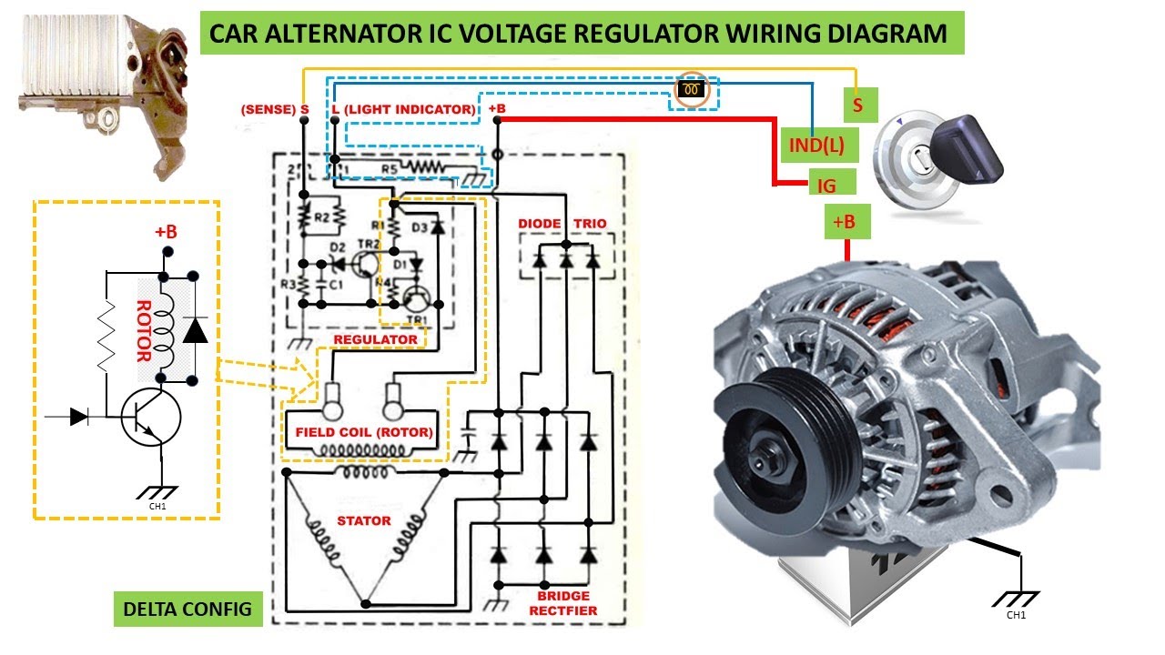
When the engine starts, the ignition switch sends power to the alternator's field winding. This creates a magnetic field. As the alternator's rotor spins (driven by the engine via the serpentine belt), this magnetic field induces AC voltage in the stator windings. The alternator's internal rectifier (usually a set of diodes) converts this AC voltage to DC voltage. The voltage regulator monitors the battery voltage and adjusts the current supplied to the field winding, ensuring a stable output voltage. This DC voltage then charges the battery and powers the vehicle's electrical system.
A simplified circuit might look like this: Battery (+) -> Ignition Switch -> Alternator Field Winding -> Ground (-) (This energizes the alternator). Then, Alternator Output (+) -> Voltage Regulator -> Battery (+) (This charges the battery). Finally, Battery (+) -> Fuses -> Vehicle Electrical System -> Ground (-) (This powers the rest of the car). Remember this is a drastically simplified example.
Real-World Use: Basic Troubleshooting
Armed with the wiring diagram, you can perform basic troubleshooting steps:
- Battery Not Charging:
- Check the belt tension. A loose belt can cause the alternator to spin too slowly.
- Use a multimeter to check the voltage at the battery terminals with the engine running. It should be between 13.8V and 14.4V. If it's significantly lower, the alternator or voltage regulator may be faulty.
- Visually inspect the wiring for corrosion, loose connections, or damaged wires. Pay close attention to the ground connections.
- Use the wiring diagram to trace the wires from the alternator to the battery and check for continuity using a multimeter. Disconnect the battery before performing continuity tests!
- Check the fuses associated with the charging system.
- Overcharging:
- This is often caused by a faulty voltage regulator. Use a multimeter to monitor the battery voltage with the engine running. If it's consistently above 14.4V, the voltage regulator likely needs replacement.
Remember: Always consult the wiring diagram for your specific vehicle before performing any electrical tests or repairs.
Safety First: Handling Electrical Components
Working with automotive electrical systems can be dangerous. Here are some critical safety precautions:
- Disconnect the Battery: Before working on any electrical components, disconnect the negative (-) battery terminal. This prevents accidental shorts and electrical shocks.
- Use Insulated Tools: Use tools with insulated handles to minimize the risk of electric shock.
- Avoid Working in Wet Conditions: Water conducts electricity, increasing the risk of electric shock.
- Be Careful Around the Alternator's Output Terminal: This terminal can carry a high voltage and current when the engine is running. Avoid touching it or any exposed wiring connected to it.
- Never Disconnect the Battery While the Engine Is Running: This can damage the alternator and other electrical components.
High-current components like the alternator and starter motor can deliver a dangerous shock. Exercise extreme caution.
Conclusion
Understanding the alternator wiring diagram with the voltage regulator is a valuable skill for any DIY mechanic or car enthusiast. It allows you to diagnose charging system problems, perform repairs, and even upgrade your vehicle's electrical system with confidence. By understanding the symbols, components, and flow of electricity, you can troubleshoot issues and keep your vehicle running smoothly.
To help you further, we have a generic alternator wiring diagram available for download. Please remember to always consult the specific diagram for your vehicle make and model for accurate information. Use it in conjunction with the knowledge you have gained from this article, and you'll be well on your way to mastering your vehicle's charging system.