Alternator With External Regulator Wiring Diagram
So, you're tackling an alternator with an external regulator, eh? Good for you! These systems, while a bit older than the internal regulator setups we see today, are still out there, especially in classic cars, heavy machinery, and marine applications. Understanding their wiring diagram is crucial for everything from basic troubleshooting to complete rewiring projects. Whether you're diagnosing a charging problem, upgrading your electrical system, or simply expanding your automotive knowledge, this guide will arm you with the insights you need.
Why This Diagram Matters
Think of the wiring diagram as the Rosetta Stone of your electrical system. Without it, you're just guessing. Specifically, this diagram allows you to:
- Diagnose charging issues: Is your battery not charging properly? The diagram helps you trace the circuit and pinpoint the fault.
- Perform accurate repairs: Knowing how the system is wired prevents costly mistakes and ensures a safe and reliable repair.
- Understand system functionality: You'll gain a deep understanding of how the alternator, regulator, and battery work together.
- Upgrade your system: Planning to upgrade your alternator or regulator? The diagram guides you in selecting the correct components and wiring them correctly.
- Rewire your classic car: Restoring a vintage vehicle often involves rewiring the entire electrical system. This diagram provides the foundation for that process.
Key Specs and Main Parts
Before we dive into the wiring, let's identify the key players and their general specifications. Keep in mind these are typical values, and your specific system may vary.
Main Components:
- Alternator: The heart of the charging system. It converts mechanical energy from the engine into electrical energy (AC), which is then rectified to DC. A common alternator output is 12-14.5 volts DC.
- External Voltage Regulator: This device monitors the battery voltage and controls the alternator's output to maintain a stable charging voltage. Regulators are typically rated for 12V or 24V systems.
- Battery: The energy storage device and provides the initial voltage for the charging system to function. A typical automotive battery is a 12V lead-acid battery.
- Ignition Switch: Provides a switched power source to the voltage regulator, enabling the charging system to activate only when the engine is running.
- Ammeter or Voltmeter: Provides a visual indication of the charging system's performance. An ammeter shows the current flow (charge or discharge), while a voltmeter displays the battery voltage.
- Fuses/Fusible Links: Critical for circuit protection. They prevent damage from overcurrent conditions.
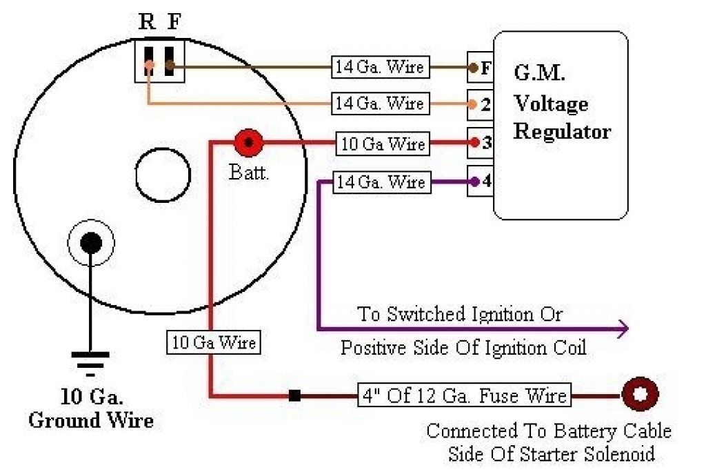
Understanding the Symbols
Wiring diagrams use standardized symbols to represent components and connections. Let's decode some common ones:
- Solid Lines: Represent wires. The thickness of the line *generally* (but not always) indicates the wire gauge (thicker lines = heavier gauge wire).
- Dashed Lines: Often indicate ground connections or less critical wiring.
- Circles with a letter inside: Represent connection points or terminals. For example, "B" for Battery, "F" for Field, "S" for Stator or Sense.
- Rectangles with wavy lines inside: Represent resistors. These limit current flow.
- Ground Symbol (usually three lines decreasing in length): Indicates a connection to the vehicle's chassis ground (negative terminal of the battery).
- Component Icons: Alternators, regulators, batteries, and switches have specific icons representing them. Consult the diagram legend for exact interpretations.
Color Coding: Wire colors are standardized, but variations exist depending on the manufacturer. A common color scheme includes:
- Red: Typically used for battery positive (+) connections.
- Black: Typically used for ground (-) connections.
- Blue/Yellow/Green: Often used for field, stator, or other control wires. Always consult the specific diagram for your vehicle.
How It Works: A Simplified Explanation
Here's a simplified overview of how the system functions:
- Ignition On: When you turn the ignition switch on, a small amount of current flows to the voltage regulator.
- Regulator Activation: The regulator senses the battery voltage. If the voltage is low, it completes the circuit to the alternator's field windings.
- Alternator Excitation: Current flowing through the field windings creates a magnetic field inside the alternator.
- Voltage Generation: As the alternator's rotor spins, the magnetic field induces a voltage in the stator windings. This AC voltage is then rectified to DC by diodes within the alternator.
- Voltage Regulation: The regulator continuously monitors the battery voltage and adjusts the current flowing through the field windings. This controls the alternator's output, maintaining a stable charging voltage (typically around 13.8-14.5 volts).
- Charging the Battery: The alternator provides current to charge the battery and power the vehicle's electrical loads.
Real-World Use: Basic Troubleshooting Tips
Using the wiring diagram, you can tackle common charging system problems:
- No Charging: Check the voltage at the alternator's output terminal with the engine running. If there's no voltage, inspect the fuse or fusible link in the battery connection. Also, check the field wire for continuity to ground – a short here can kill the alternator output. If voltage is present but low, suspect a faulty regulator or a bad alternator.
- Overcharging: This usually indicates a faulty voltage regulator. Replace the regulator and re-test. Also, ensure the regulator is properly grounded, as a poor ground can lead to overcharging.
- Battery Drain: If the battery is constantly draining, even with the engine off, use the diagram to trace potential parasitic draws. Disconnect circuits one by one to isolate the source of the drain. A faulty diode in the alternator can sometimes cause a parasitic drain.
- Wiring Problems: Inspect all wiring connections for corrosion, loose terminals, and damaged insulation. Clean and tighten any suspect connections. Use a multimeter to check for voltage drops across connections. A significant voltage drop indicates resistance and a potential problem.
Safety First!
Working with electrical systems can be dangerous. Here are some critical safety precautions:
- Disconnect the Battery: Always disconnect the negative battery cable before working on the electrical system. This prevents accidental shorts and potential electrical shocks.
- High Voltage: The alternator can produce high voltages, especially if the regulator is faulty. Be cautious when testing the alternator's output.
- Fuses are Your Friend: Never bypass fuses or fusible links. They are there to protect the system from overcurrent damage. Always replace a blown fuse with one of the same amperage rating.
- Wear Safety Glasses: Protect your eyes from sparks and debris.
Important Note: The exact wiring configuration will vary depending on the make, model, and year of your vehicle. Always consult the specific wiring diagram for your application.
Understanding the wiring diagram for an alternator with an external regulator empowers you to confidently diagnose, repair, and upgrade your charging system. Remember to take your time, double-check your work, and prioritize safety. With the right knowledge and tools, you can tackle these projects with confidence.
We have a downloadable alternator with external regulator wiring diagram file available for you. This diagram provides a visual aid and detailed information to help you understand and troubleshoot your charging system. Please contact us to access the file.