
Altima Nissan Cvt Transmission Diagram
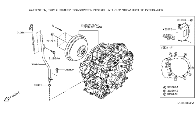
The Continuously Variable Transmission (CVT) in Nissan Altimas, especially those manufactured after the early 2000s, is a sophisticated piece of engineering. Understanding its operation and having access to a detailed diagram is invaluable, whether you're performing routine maintenance, diagnosing a problem, or even considering modifications. This article serves as your guide to interpreting a typical Altima CVT transmission diagram, covering its essential components, how it works, and practical troubleshooting tips. We also have the diagram available for download, which we'll mention at the end.
Purpose of Understanding the CVT Transmission Diagram
Why bother learning about the CVT and its diagram? The answer lies in empowerment. A diagram allows you to:
- Diagnose Problems Accurately: Pinpoint the source of issues like slipping, jerking, or complete failure.
- Perform Targeted Repairs: Avoid unnecessary component replacements by identifying the specific part causing the problem.
- Understand Maintenance Procedures: Grasp the importance of regular fluid changes and other preventative measures.
- Consider Modifications (with Caution): If you're thinking about enhancing your Altima's performance, understanding the CVT's limitations is crucial.
- Educate Yourself: Gain a deeper appreciation for the technology that powers your vehicle.
Key Specs and Main Parts
Before diving into the diagram, let's define some key terms and identify the main parts of a typical Altima CVT. Remember, specific layouts can vary slightly depending on the year and model.
- Primary Pulley (Input Pulley): Connected to the engine, it receives power and initiates the transmission process.
- Secondary Pulley (Output Pulley): Connected to the drivetrain, it transmits power to the wheels.
- Steel Belt or Chain: Connects the primary and secondary pulleys, transmitting torque between them. The strength and design of the belt is *critical* to the CVT's lifespan.
- Valve Body: The hydraulic control center of the CVT. It contains numerous solenoids and valves that regulate fluid pressure to control pulley ratios and clutch engagement.
- TCM (Transmission Control Module): The computer that controls the CVT's operation. It receives inputs from various sensors and uses this information to adjust pulley ratios and manage other functions.
- Fluid Pump: Provides hydraulic pressure necessary for the valve body to function and for lubrication.
- Torque Converter (or Fluid Coupling): Connects the engine to the primary pulley, allowing for smooth starts and preventing engine stalling. In some newer designs, a damper system is integrated directly.
- Sensors: Numerous sensors monitor various parameters such as input speed, output speed, fluid temperature, and throttle position.
- Planetary Gearset (in some models): Some CVT designs incorporate a planetary gearset for reverse or for extending the overall gear ratio range.
Symbols and Diagram Interpretation
Understanding the symbols used in the diagram is essential for proper interpretation. Here's a general guide:
- Solid Lines: Typically represent hydraulic lines carrying transmission fluid. Different line thicknesses might indicate the pressure rating or flow capacity of the line.
- Dashed Lines: Usually represent electrical wiring or control signals.
- Color Coding: Colors are often used to distinguish different fluid circuits (e.g., lubrication, control pressure, cooling). Refer to the diagram's legend for specific color assignments.
- Rectangles: Can represent solenoids, valves, or other electrical components. The diagram might contain specific identifiers inside the rectangle, such as "SLT" for Shift Line pressure solenoid.
- Circles: Often represent sensors or pressure transducers.
- Arrows: Indicate the direction of fluid flow or electrical signal flow.
- Labels: Crucial for identifying specific components and their functions. Pay close attention to abbreviations and acronyms.
- Block Diagrams: Show the relationship between different systems or components, without necessarily detailing the physical layout.
Pay close attention to the legend or key provided with the diagram. This will explain the specific symbols and color codes used in that particular diagram.
How the Altima CVT Works
The CVT's primary advantage is its ability to provide a seamless and continuously variable gear ratio. Here's a simplified explanation:
- The engine's power is transmitted to the primary pulley via the torque converter.
- The primary and secondary pulleys are connected by the steel belt.
- The effective diameter of each pulley is controlled by hydraulic pressure, which is regulated by the valve body.
- The TCM determines the optimal pulley ratio based on factors such as vehicle speed, engine load, and driver input.
- By continuously adjusting the pulley ratios, the CVT can provide the ideal gear ratio for any given driving condition, maximizing fuel efficiency and performance.
- The output pulley then transfers power to the differential and ultimately the wheels.
Unlike traditional automatic transmissions with fixed gear ratios, the CVT eliminates shift points, resulting in a smoother and more efficient driving experience. This efficiency, however, comes at the cost of complexity and, in some cases, durability.
Real-World Use and Basic Troubleshooting
Here are a few basic troubleshooting tips you can perform *after consulting the diagram and service manual*:
- Slipping or Jerking: This is often caused by low fluid level, contaminated fluid, or a faulty valve body. Check the fluid level and condition. Refer to the diagram to locate the fill and drain plugs.
- Whining Noise: Could indicate a failing fluid pump or a damaged belt. Inspect the pump and belt for signs of wear or damage. The diagram will show the pump's location and fluid flow path.
- Transmission Overheating: Check the cooling system, including the transmission cooler and its lines. The diagram will show the location of the cooler and its connections to the transmission.
- Trouble Codes: Use an OBD-II scanner to retrieve trouble codes. The diagram can help you identify the components related to those codes. For example, a code related to a specific solenoid can be traced back to its location on the valve body diagram.
Important: Always consult the factory service manual for specific diagnostic procedures and repair instructions. The diagram is a tool to aid in diagnosis, not a substitute for proper training and experience.
Safety Considerations
Working on a CVT transmission involves several safety risks:
- High Pressure: The hydraulic system operates at high pressure. Always relieve pressure before disconnecting any lines or components. Failure to do so could result in serious injury.
- Hot Fluid: Transmission fluid can be extremely hot. Allow the transmission to cool down before working on it.
- Electrical Components: The CVT contains numerous electrical components, including solenoids and sensors. Disconnect the battery before working on these components to prevent electrical shock.
- Lifting and Support: Always use proper lifting and support equipment when working under a vehicle. Never rely on a jack alone.
- Fluid Disposal: Dispose of used transmission fluid properly. It is a hazardous waste and should not be poured down drains or onto the ground.
Never attempt to disassemble or repair the CVT unless you have the proper tools, training, and experience. Incorrect procedures can damage the transmission and create a safety hazard.
The Valve body is a very sensitive component, any contaminations will affect it.
Special Attention needs to be addressed to the steel belt because is a source of many problems.
We have a detailed Altima CVT transmission diagram available for download. This diagram will provide you with a visual representation of the transmission's internal components and hydraulic circuits. Contact us to get access to the file.