Assembly Wheel Hub Front Wheel Bearing Diagram
Alright, let's dive into the anatomy of a front wheel hub assembly and its wheel bearing. We're going to break down a typical diagram you might encounter when tackling front-end work on your vehicle. This knowledge is crucial whether you're replacing a worn-out bearing, diagnosing a suspension issue, or just wanting a deeper understanding of your car's mechanics. I'm assuming you have some wrenching experience, so we'll skip the absolute basics and focus on interpreting the diagram itself.
Purpose of the Diagram
Why bother with a diagram? Simple. Accurate repairs. These diagrams, often called exploded views or assembly drawings, are your roadmap. They show exactly how the components fit together, the order they should be assembled, and, crucially, the part numbers you'll need. Trying to reassemble a hub assembly from memory is a recipe for disaster. You risk damaging components, introducing play (looseness), and compromising safety. Beyond repairs, studying the diagram helps you understand the flow of force through the assembly, which is invaluable for diagnosing problems and even planning modifications.
Key Specs and Main Parts
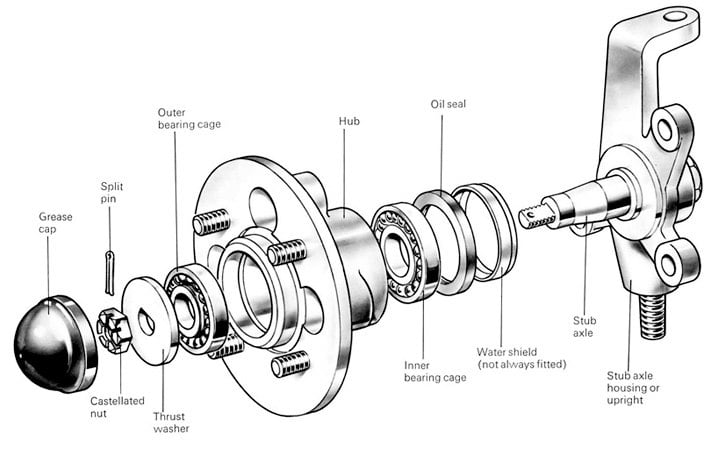
Before we jump into the symbology, let's identify the key components usually shown in a front wheel hub assembly diagram:
- Hub Assembly: The central component that rotates with the wheel. It's typically made of forged steel and has a splined center to accept the axle shaft.
- Wheel Bearing: This is the heart of the assembly, allowing smooth rotation between the hub and the steering knuckle (explained below). Most modern vehicles use sealed hub bearing units – pre-assembled, pre-greased, and designed for ease of replacement. Older vehicles might have tapered roller bearings that require manual packing and adjustment.
- Steering Knuckle (or Spindle): This is the structural component that connects the suspension to the wheel hub. It pivots to allow steering and provides mounting points for the brake caliper.
- Axle Shaft (or CV Axle): Transmits power from the transmission to the wheel hub. It passes through the center of the hub and is secured with a nut. For front-wheel drive vehicles, this is a constant velocity (CV) axle allowing power transfer at various steering angles.
- Hub Nut (or Axle Nut): Secures the axle shaft to the hub. This nut is typically torqued to a very high specification and often requires a new nut with each installation.
- ABS Sensor and Tone Ring: Modern vehicles have an Anti-lock Braking System (ABS). The sensor reads the speed of the wheel from the tone ring (a toothed ring on the hub or axle) and sends this information to the ABS control module.
- Dust Shields/Seals: These protect the bearing from contaminants like dirt, water, and road salt.
- Retaining Rings (Circlips): Used to hold the bearing in place within the hub or knuckle.
- Wheel Speed Sensor Wiring: The wiring harness which delivers data to the ABS control unit.
The diagram will also list critical specifications, often in a separate table or notes section. Look for:
- Torque Specifications: The tightening torque for all bolts and nuts, especially the hub nut. Using the correct torque is critical to the longevity and safety of the assembly.
- Bearing Preload: For older-style tapered roller bearings, the diagram will specify the correct preload (the amount of tension on the bearing). This is adjusted using a nut or shims. Modern hub units don't require preload adjustment.
- Part Numbers: Essential for ordering the correct replacement parts.
- Grease Types: If applicable, the diagram will specify the correct type of grease to use for packing bearings or lubricating components.
Symbols – Decoding the Diagram
Diagrams use a standardized set of symbols to convey information efficiently:
- Solid Lines: Represent visible edges of components.
- Dashed Lines: Indicate hidden edges or internal features.
- Center Lines: Thin lines with alternating long and short dashes, indicating the center of a circular feature or the axis of symmetry.
- Section Lines (Hatching): Parallel lines used to indicate a cut-away view, revealing internal details. Different hatching patterns can represent different materials.
- Arrows: Indicate the direction of force or movement. For example, arrows might show how to apply pressure to press a bearing into place.
- Callouts: Numbered or lettered balloons pointing to specific components. These callouts are referenced in a parts list or description table.
- Exploded Views: The components are shown slightly separated from each other, illustrating the order of assembly.
- Tolerance Symbols: Indicate the acceptable range of variation in dimensions. You likely won't see these on a basic assembly diagram, but they're common in engineering drawings.
- Color Coding: Some diagrams use color to distinguish between different materials or components. A legend will explain the color scheme.
How It Works
The front wheel hub assembly's primary function is to allow the wheel to rotate smoothly while supporting the vehicle's weight and transmitting driving forces. Here's the breakdown:
- The wheel bearing provides a low-friction interface between the rotating hub and the stationary steering knuckle.
- The hub is bolted to the wheel.
- The axle shaft (in driven wheels) transmits torque from the transmission to the hub, causing the wheel to rotate.
- The steering knuckle connects the hub assembly to the suspension components, allowing the wheel to be steered.
- The ABS sensor monitors the wheel's speed to prevent wheel lockup during braking.
The key is the bearing's ability to handle both radial load (the weight of the vehicle pressing down) and axial load (forces acting along the axis of the wheel, such as cornering forces). A damaged or worn bearing will exhibit play (looseness) and can lead to noise, vibration, and ultimately, catastrophic failure.
Real-World Use – Basic Troubleshooting
Let's say you suspect a bad wheel bearing. Here's how a diagram can help with troubleshooting:
- Identify the Components: Use the diagram to locate the bearing and surrounding components. Knowing their arrangement will help you visually inspect them.
- Check for Play: With the wheel off the ground, try to move it back and forth. Excessive play indicates a worn bearing or other suspension issues. Refer to the diagram to see if there are any adjustable components that might be loose.
- Listen for Noise: Rotate the wheel by hand. A grinding, rumbling, or clicking noise coming from the hub area is a strong indication of a bad bearing. The diagram can help you pinpoint the source of the noise.
- Inspect the ABS Sensor: A faulty ABS sensor can cause erratic braking. Use the diagram to locate the sensor and check its wiring for damage.
- Verify Proper Torque: If you've recently replaced the hub or axle, double-check the torque of the hub nut. Under-torquing can lead to premature bearing failure. Use the diagram to find the correct torque specification.
Safety – Risky Components
Working on front wheel hub assemblies can be dangerous if you're not careful. Here are a few things to keep in mind:
- Spring Compression: Many front suspension systems use coil springs or struts that are under tremendous compression. Never attempt to disassemble a strut without the proper spring compressor tool. Serious injury or death can result.
- Hub Nut Torque: As mentioned earlier, the hub nut is torqued to a very high specification. Using an impact wrench without a torque stick can easily over-tighten the nut, damaging the bearing or axle. Always use a torque wrench to tighten the hub nut to the specified torque.
- ABS Sensors: Handle ABS sensors with care. They are sensitive to static electricity and physical damage. Disconnect the battery before working on the ABS system.
- Brake Components: Be mindful of brake lines and components. Damaging a brake line can result in a loss of braking power.
- Personal Protective Equipment: Always wear safety glasses and gloves when working on automotive components.
Remember, if you're not comfortable performing any of these procedures, consult a qualified mechanic.
Understanding the diagram is the first step in tackling front wheel hub assembly work with confidence. With a good diagram and a little patience, you can save money and gain a valuable understanding of your vehicle's mechanics.
We have a sample front wheel hub assembly diagram file available for download. This file provides a visual aid to help you better understand the concepts discussed in this article.