
Auto Air Conditioning Schematic Diagram
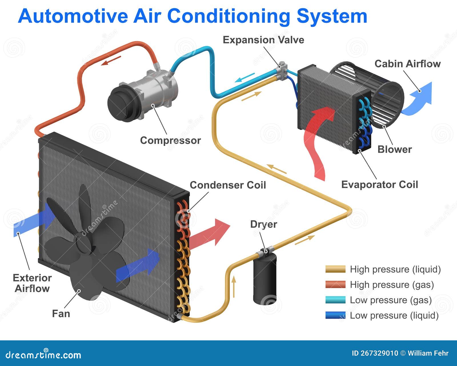
Understanding your car's air conditioning (A/C) system can seem daunting, but armed with the right knowledge and, most importantly, the A/C schematic diagram, you can diagnose problems, perform basic repairs, and even customize your system. This article will break down the schematic diagram, explaining its purpose, key components, symbols, and how to use it for real-world troubleshooting. We're assuming you've got some experience under the hood and are ready to dive a little deeper into the technical aspects of your car's climate control.
Purpose of the A/C Schematic Diagram
The A/C schematic diagram is essentially a roadmap of your vehicle's air conditioning system. Its primary purpose is to provide a visual representation of all the components and their interconnections. This allows you to:
- Diagnose Problems: By tracing the circuit paths and identifying potential failure points, you can pinpoint the source of A/C issues, such as a lack of cooling, intermittent operation, or unusual noises.
- Perform Repairs: The diagram helps you understand how components are connected, making it easier to replace parts, repair wiring, and properly reassemble the system.
- Understand System Operation: Even if you're not experiencing problems, studying the diagram can help you understand the overall flow of refrigerant and the function of each component.
- Customize and Modify: For more advanced DIYers, the schematic is invaluable for modifications like adding auxiliary fans, upgrading components, or even retrofitting A/C into a vehicle that didn't originally have it.
Key Specs and Main Parts
Before we delve into the diagram, let's review the key components of a typical automotive A/C system. These components will be represented in the schematic:
- Compressor: The heart of the system. It circulates and compresses the refrigerant, increasing its pressure and temperature. Compressors can be clutch-type (cycled on/off) or variable displacement.
- Condenser: Located at the front of the vehicle, the condenser dissipates heat from the high-pressure, high-temperature refrigerant, causing it to condense into a liquid.
- Receiver-Drier (or Accumulator): This component filters out moisture and debris from the refrigerant. The Receiver-Drier is typically used with a Thermal Expansion Valve (TXV), while the Accumulator is used with an Orifice Tube.
- Expansion Valve (TXV) or Orifice Tube: This metering device controls the flow of refrigerant into the evaporator, reducing the pressure and causing the refrigerant to expand and cool. A TXV modulates refrigerant flow based on superheat, whereas an orifice tube provides a fixed restriction.
- Evaporator: Located inside the vehicle's dashboard, the evaporator absorbs heat from the cabin air, causing the refrigerant to boil and turn into a vapor. This is where the cooling actually happens.
- Blower Motor: Circulates air across the evaporator to distribute the cool air into the cabin.
- Pressure Switches: These switches monitor the refrigerant pressure and protect the system from damage. Common types include high-pressure cut-off switches and low-pressure cut-off switches.
- Refrigerant: The working fluid that carries heat throughout the system. Modern vehicles typically use R-134a or R-1234yf.
- Wiring and Control System: This includes the wiring harness, relays, fuses, and the A/C control panel inside the vehicle, which allows the driver to control the system.
Symbols and Conventions
Understanding the symbols used in the A/C schematic diagram is crucial for interpreting it correctly. While there may be slight variations between diagrams from different manufacturers, here are some common conventions:
- Lines: Solid lines generally represent wiring. Dashed lines may represent vacuum lines or refrigerant lines. The thickness of a line can sometimes indicate the wire gauge (thicker lines = larger gauge wire).
- Colors: Wiring is often color-coded, with each color representing a specific function or signal. The diagram will usually include a legend explaining the color codes (e.g., Red = Power, Black = Ground, Blue = Signal).
- Icons: Specific icons represent each component (e.g., a squiggly line inside a circle might represent a resistor, a rectangle with diagonal lines might represent a condenser). The diagram will have a legend explaining the icons used.
- Relays: Relays are shown as a coil and a set of contacts. The coil, when energized, closes or opens the contacts, allowing current to flow to a component.
- Grounds: Ground symbols indicate where the circuit connects to the vehicle's chassis, providing a return path for the current.
- Fuses: Fuses are shown as a small line or rectangle with a number indicating the fuse's amperage rating.
- Connectors: Connectors are shown as mating symbols indicating where wires plug into each other. These are important for troubleshooting wiring issues.
Always refer to the diagram's legend for clarification on any symbols or color codes you're unsure about.
How It Works: Tracing the Circuit
To understand how the A/C system works based on the schematic, let's trace the circuit, beginning with the driver turning on the A/C:
- The driver activates the A/C system via the control panel. This sends a signal to the vehicle's computer (ECU/PCM) or directly to a relay.
- The ECU/PCM, based on various inputs (engine temperature, throttle position, etc.), decides whether to engage the A/C compressor.
- If conditions are right, the ECU/PCM activates the A/C compressor relay.
- The A/C compressor relay sends power to the compressor clutch, engaging the compressor.
- The compressor begins to circulate refrigerant through the system.
- Pressure switches monitor the refrigerant pressure. If the pressure is too low or too high, the switches will interrupt the circuit to protect the compressor.
- The blower motor is activated to circulate air across the evaporator, cooling the cabin.
By tracing this circuit on the schematic, you can see the flow of electricity and understand how each component interacts with the others. Pay attention to the wiring colors, connector locations, and the location of any fuses or relays in the circuit.
Real-World Use: Basic Troubleshooting Tips
Here's how you can use the A/C schematic for basic troubleshooting:
- No A/C at all: Start by checking the fuses and relays associated with the A/C system. The schematic will show you exactly which fuses and relays to check and their location. Use a multimeter to test the fuses for continuity.
- Compressor not engaging: Use the schematic to trace the wiring from the A/C control panel to the compressor relay to the compressor clutch. Check for voltage at each point in the circuit. If you find a point where voltage is missing, that's likely the source of the problem. Check the pressure switches, too; they could be preventing the compressor from engaging if the refrigerant level is too low.
- Weak Cooling: This could be due to low refrigerant, a faulty expansion valve, or a clogged condenser. The schematic won't directly diagnose these issues, but it can help you locate the components and check their wiring and connections. A manifold gauge set is needed to check refrigerant pressures.
- Intermittent Operation: This is often caused by loose connections or faulty relays. Use the schematic to identify the key connections and relays in the circuit and check them for corrosion or damage.
Always consult the vehicle's service manual for specific troubleshooting procedures and diagnostic codes.
Safety Considerations
Working on the A/C system involves certain risks:
- High Pressure: The A/C system contains high-pressure refrigerant. Never disconnect any refrigerant lines without properly discharging the system using the correct equipment. Refrigerant can cause frostbite if it comes into contact with skin.
- Electrical Hazards: The A/C system uses electrical components. Disconnect the battery before working on any electrical components to avoid electric shock.
- Refrigerant Toxicity: Refrigerant can be harmful if inhaled. Work in a well-ventilated area.
If you're not comfortable working with refrigerant or electrical components, it's best to take your vehicle to a qualified A/C technician.
We have a sample A/C schematic diagram available for download, which can serve as a valuable resource as you learn to interpret these diagrams. With practice and a solid understanding of the system, you'll be able to diagnose and repair your vehicle's A/C system with confidence.