
Auto Electrical Wiring Diagram Symbols
Hey there, fellow gearheads! Ever stared at a spaghetti bowl of wires under your dashboard and wished you had a decoder ring? That's where auto electrical wiring diagrams come in. This article is your guide to understanding these diagrams, turning that daunting maze into a roadmap for repairs, modifications, and even just a deeper understanding of your vehicle's electrical system.
Why Bother with Wiring Diagrams?
Think of an auto electrical wiring diagram as the schematic for your car's nervous system. It's a visual representation of how all the electrical components – lights, sensors, actuators, modules – are interconnected. Why is understanding this crucial? Several reasons:
- Troubleshooting Electrical Issues: When a circuit malfunctions – a light flickers, a sensor throws a code – the diagram allows you to trace the wiring and pinpoint the source of the problem (short circuit, open circuit, bad ground, etc.).
- Performing Repairs: Replacing a damaged wire or component becomes much easier when you know exactly where it connects to other parts of the system.
- Adding Aftermarket Accessories: Installing a new stereo, alarm system, or auxiliary lights requires tapping into existing circuits. A wiring diagram helps you do this safely and correctly, avoiding damage or electrical fires.
- Understanding Your Vehicle: Even if you're not actively fixing something, studying the diagram can significantly improve your knowledge of your car's inner workings.
Key Specs and Main Parts of a Wiring Diagram
Before diving into the symbols, let's understand the basic structure of a wiring diagram. Key elements include:
- Power Source: Typically, the battery and alternator are the primary power sources. The diagram will show how these are connected to the rest of the system, often via a fuse box or power distribution center.
- Ground: Every electrical circuit needs a return path to the battery. This is achieved through the chassis of the car, which acts as a common ground. Ground connections are clearly marked in the diagram.
- Switches: These control the flow of electricity to various components. Common examples include ignition switches, headlight switches, and window switches.
- Relays: Relays are electromagnetic switches that allow a low-current circuit to control a high-current circuit. They're often used to power things like headlights, horns, and fuel pumps.
- Fuses and Circuit Breakers: These protect the electrical system from overloads. They're designed to break the circuit if too much current flows through it, preventing damage to wiring and components.
- Wiring Harnesses: These are bundles of wires that are grouped together for organization and protection. The diagram will show how the wires are routed through the vehicle.
- Connectors: These are used to join wires together and to connect components to the wiring harness. The diagram will often show the connector's pinout (the arrangement of the pins).
- Electronic Control Units (ECUs): Modern vehicles rely heavily on ECUs (also sometimes called modules or controllers) to manage various systems, such as the engine, transmission, and anti-lock brakes. The diagram will show how these ECUs are connected to the sensors and actuators they control.
Decoding the Symbols: Your Electrical Rosetta Stone
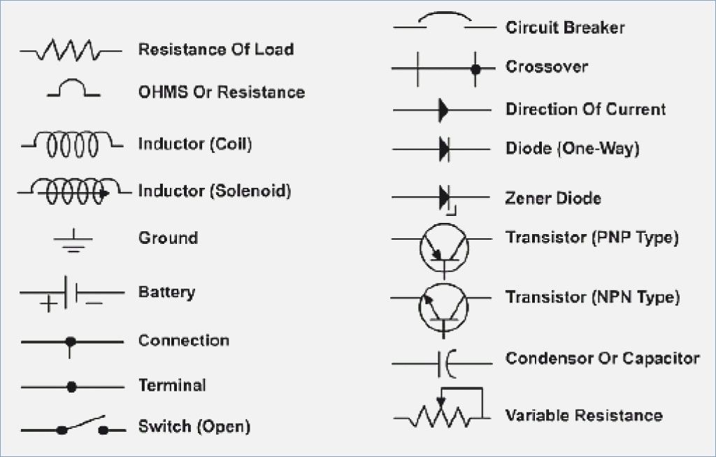
This is where the magic happens. Wiring diagrams use standardized symbols to represent different components and wires. Here's a breakdown of some of the most common ones:
Lines and Colors
- Solid Lines: Represent wires. Thicker lines might indicate wires carrying higher current.
- Dashed Lines: Can represent shielded wires or connections to ground.
- Colors: Each wire in the vehicle has a specific color code (e.g., Red/White, Black/Yellow). These colors are crucial for identifying the correct wire in a harness. The diagram will include a color legend.
Component Symbols
Note: Symbol variations exist between manufacturers and even different models of the same manufacturer. Always refer to the specific wiring diagram for your vehicle.
- Battery: Represented by a series of long and short parallel lines. The longer line indicates the positive (+) terminal, and the shorter line indicates the negative (-) terminal.
- Ground: Several variations exist, including:
- A series of descending horizontal lines connected to a vertical line.
- An inverted triangle pointing downwards.
- Resistor: A zig-zag line.
- Capacitor: Two parallel vertical lines.
- Diode: A triangle pointing towards a vertical line.
- Fuse: A small "S" shape inside a rectangle, or just a rectangle with the word "FUSE" inside.
- Relay: A coil representing the electromagnet and a switch representing the contacts. You'll typically see the relay coil controlling the position of the switch.
- Switch: A break in the wire with a lever that can connect or disconnect the circuit.
- Light Bulb: A circle with an "X" inside.
- Motor: A circle with an "M" inside.
- Connector: Two interlocking shapes. The diagram may include a connector pinout, showing which wire connects to which pin on the connector.
Numerical and Alphanumeric Designations
Wiring diagrams often include numbers and letters next to wires and components. These designations are used to identify specific wires, connectors, and terminals. For example, you might see "12V" next to a wire, indicating that it carries 12 volts. Or you might see a connector labeled "X123", which corresponds to a physical connector in the vehicle.
How It Works: Tracing a Circuit
Let's imagine you're troubleshooting a faulty headlight. Here's how you'd use a wiring diagram:
- Locate the Headlight Circuit: Find the section of the diagram that shows the headlight circuit.
- Identify the Power Source: Trace the wire from the headlight back to the power source (likely the battery, through a fuse and a relay).
- Check the Switch: Verify that the headlight switch is functioning correctly. The diagram will show the switch's position in the circuit.
- Follow the Ground: Trace the ground wire from the headlight to the chassis ground. Make sure the ground connection is clean and secure.
- Use a Multimeter: With the diagram in hand, use a multimeter to check for voltage and continuity at various points in the circuit. This will help you identify where the break in the circuit is.
Real-World Use: Basic Troubleshooting Tips
- Start with the Basics: Check the fuse first! A blown fuse is the most common cause of electrical problems.
- Look for Obvious Damage: Inspect the wiring and connectors for any signs of damage, such as frayed wires, corroded terminals, or loose connections.
- Use a Multimeter: A multimeter is your best friend when troubleshooting electrical problems. Learn how to use it to check for voltage, continuity, and resistance.
- Isolate the Problem: If you have multiple symptoms, try to isolate the problem to a specific circuit or component.
- Don't Be Afraid to Ask for Help: If you're stuck, don't hesitate to consult a professional mechanic or online forum.
Safety First: Respect the Electricity
Working with automotive electrical systems can be dangerous. Always follow these safety precautions:
- Disconnect the Battery: Before working on any electrical circuit, disconnect the negative terminal of the battery. This will prevent accidental shorts and shocks.
- Be Careful with High-Voltage Components: Components like the ignition coil and certain sensors can carry high voltages. Avoid touching these components when the engine is running.
- Never Bypass Fuses: Fuses are there to protect the electrical system. Never bypass a fuse or replace it with one of a higher amperage rating.
- Work in a Well-Ventilated Area: When soldering or working with flammable materials, work in a well-ventilated area.
- Use Proper Tools: Use insulated tools designed for automotive electrical work.
Dangerous Components
Some components carry more risk than others. ECUs can be sensitive to voltage spikes, so avoid static discharge when handling them. The SRS (Supplemental Restraint System), including airbags, contains explosive components. Never attempt to diagnose or repair the SRS system without proper training and equipment, as accidental deployment can cause serious injury.
Understanding auto electrical wiring diagrams is a skill that empowers you to diagnose and repair electrical issues with confidence. Start small, practice tracing circuits, and always prioritize safety. With a little patience and the right knowledge, you can tame that spaghetti bowl of wires and keep your ride running smoothly. Good luck, and happy wrenching!
Remember, we've got a general auto electrical wiring diagram file that may be useful as a reference point. Consider downloading it for a more detailed visual aid.