Auto Electrical Wiring Diagrams Free
Welcome, fellow gearheads and shade-tree mechanics! Let's dive into the often-intimidating, but ultimately crucial, world of automotive electrical wiring diagrams. These schematics are the Rosetta Stone of your car's electrical system, and understanding them unlocks a world of troubleshooting, repair, and modification possibilities.
Purpose: Why You Need a Wiring Diagram
Imagine trying to fix a short circuit by randomly snipping wires. Not a pretty picture, right? A wiring diagram is your guide, preventing such automotive mayhem. It serves several vital purposes:
- Troubleshooting Electrical Issues: Pinpoint the exact location of faults like short circuits, open circuits, and voltage drops. Without a diagram, you're flying blind.
- Performing Repairs: Understand how components are connected, making it easier to replace faulty parts or repair damaged wiring harnesses.
- Installing Aftermarket Accessories: Safely and correctly install stereos, alarms, lighting, or other accessories. Knowing where to tap into the power or signal lines is critical.
- Learning the Electrical System: Gain a deeper understanding of how your car's electrical system functions as a whole, and how individual components interact.
- Modifying the Electrical System: Make informed and safe modifications to the electrical system, such as adding relays or custom circuits. Proper planning prevents fried ECUs!
Key Specs and Main Parts of a Wiring Diagram
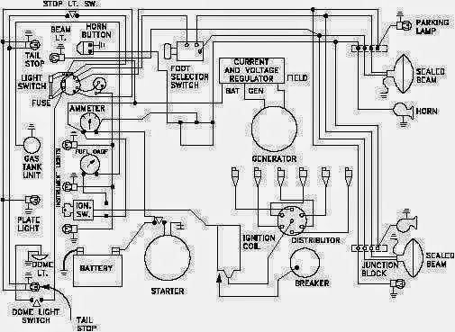
A comprehensive wiring diagram will typically include the following:
- Component Symbols: Standardized symbols representing various electrical components (relays, fuses, switches, sensors, etc.).
- Wiring Lines: Lines representing wires connecting the components. These lines may be color-coded and numbered to indicate wire gauge (thickness) and function.
- Wire Colors: Crucially important! Wire colors (e.g., BLK for black, RED for red, GRN for green, YEL for yellow, BLU for blue, WHT for white) indicate the actual color of the wire in the vehicle's wiring harness. These are often abbreviated.
- Ground Points: Symbols indicating where the circuit is grounded to the vehicle's chassis (usually marked with a ground symbol). Good grounds are essential for proper circuit operation.
- Connectors: Symbols representing electrical connectors that join sections of the wiring harness. They often have pin numbers associated with them.
- Voltage and Current Values: Some diagrams may include information about expected voltage or current levels in certain circuits.
- Fuses and Circuit Breakers: Symbols that represents the fuse and breaker, with it Ampere rating (e.g., 10A).
- Relay Logic: Details on how relays are triggered and what circuits they control.
- ECU Pinouts: Diagrams of the Engine Control Unit (ECU) connector, showing the function of each pin. This is crucial for advanced diagnostics and tuning.
Decoding the Symbols: Lines, Colors, and Icons
Understanding the symbols is paramount to interpreting a wiring diagram. Here’s a breakdown of common elements:
Lines: The Electrical Pathways
- Solid Lines: Represent standard electrical wires.
- Dashed Lines: May indicate shielded wires, data lines (like those used in CAN bus systems), or less critical connections.
- Line Thickness: Can sometimes indicate wire gauge (thicker lines often represent larger gauge wires, handling more current), but not always reliable – always check for explicit wire gauge markings.
Colors: The Wire Identifiers
Wire colors are represented by abbreviations. Here are a few examples:
- BLK: Black (Ground)
- RED: Red (Power)
- WHT: White
- GRN: Green
- BLU: Blue
- YEL: Yellow
- BRN: Brown
- ORG: Orange
- PNK: Pink
- LT BLU: Light Blue
- DK GRN: Dark Green
Often, wires will be striped with another color (e.g., GRN/WHT would be a green wire with a white stripe). The first color listed is the base color, and the second is the stripe color.
Icons: The Component Representations
Component icons are standardized, but can vary slightly between manufacturers. Some common ones include:
- Resistor: A zig-zag line.
- Capacitor: Two parallel lines.
- Inductor (Coil): A coiled line.
- Switch: A line that can be opened or closed.
- Relay: A coil (the relay's electromagnet) and a set of switch contacts that the coil controls.
- Diode: A triangle pointing towards a line.
- Transistor: A three-terminal device that can amplify or switch electronic signals.
- Ground: A symbol resembling an inverted pyramid or a series of horizontal lines getting shorter.
- Fuse: Usually a squiggly line inside a rectangle or circle.
- ECU: A rectangle, often with pin numbers labeled.
How It Works: Tracing the Circuit
The key to using a wiring diagram is to trace the circuit you're interested in. Start at the power source (usually the battery), follow the wire through fuses, switches, relays, and other components, and finally to the load (the device you're trying to power, like a light bulb or motor). Pay attention to ground points along the way. A break in the circuit anywhere along this path will prevent the load from operating.
Example: Let's say your headlights aren't working. Consult the wiring diagram for the headlight circuit. Locate the headlight switch, the headlight relay (if equipped), the fuses protecting the circuit, and the headlights themselves. Trace the path of electricity from the battery, through these components, and back to ground. If you find a blown fuse, that's likely your problem. If the fuse is good, you'll need to test the switch, relay, and wiring for continuity and voltage.
Real-World Use: Basic Troubleshooting Tips
Here are a few basic troubleshooting tips using a wiring diagram:
- No Power? Check the fuse first. It's the most common point of failure. Use a multimeter to test for continuity across the fuse.
- Voltage Drop? Use a multimeter to measure the voltage at various points along the circuit. A significant voltage drop indicates a high-resistance connection, often caused by corrosion or loose connections.
- Short Circuit? A short circuit occurs when a wire accidentally touches ground. This will usually blow a fuse. Use a multimeter to check for continuity between the wire and ground. Disconnect the battery before testing for continuity!
- Open Circuit? An open circuit occurs when a wire is broken or a connection is loose. Use a multimeter to check for continuity along the wire.
Remember to always disconnect the battery before working on electrical circuits. This prevents accidental short circuits and potential damage to electrical components.
Safety: Identifying Risky Components
Some components handle high voltages or currents and can be dangerous. Be especially careful when working with:
- Ignition System: Coils and ignition control modules can generate very high voltages (thousands of volts).
- Fuel Injection System: Fuel injectors operate at relatively high voltages.
- Charging System: The alternator can produce high currents, and the battery can store a significant amount of energy.
- Airbag System: Airbags are deployed by an explosive charge. Never probe or tamper with airbag wiring unless you are specifically trained to do so. Accidental deployment can cause serious injury. Always disconnect the battery and wait at least 10 minutes before working on the airbag system.
Always consult the vehicle's service manual for specific safety precautions related to the electrical system.
Understanding and utilizing auto electrical wiring diagrams empowers you to diagnose, repair, and modify your vehicle's electrical systems with confidence. They provide a roadmap to the complex network of wires and components, turning electrical mysteries into manageable challenges.
We have a wiring diagram file available for download. Use it responsibly and safely!