Auto Meter Tachometer Wiring Diagram
So, you're looking to wire up an Auto Meter tachometer, or maybe you're troubleshooting an existing installation. Good choice! Auto Meter is a respected name, but even the best equipment needs to be wired correctly. A solid understanding of the wiring diagram is crucial, whether you're upgrading your dash, diagnosing a problem, or just satisfying your curiosity. This article provides a comprehensive guide to deciphering Auto Meter tachometer wiring diagrams, helping you get your tach working flawlessly and safely.
Why This Diagram Matters
Forget about haphazardly connecting wires and hoping for the best. A wiring diagram is your roadmap. It's essential for several reasons:
- Accurate Installation: Ensures your tachometer receives the correct power, ground, and signal, avoiding damage and ensuring accurate readings.
- Troubleshooting: Helps you pinpoint issues if your tachometer isn't working correctly. You can systematically check connections and identify breaks in the circuit.
- Customization: If you're modifying your electrical system, understanding the diagram allows you to integrate the tachometer seamlessly.
- Learning: It's a fantastic way to deepen your understanding of automotive electrical systems.
Key Specs and Main Parts
Before diving into the diagram, let's cover the key components and specifications you'll encounter:
Tachometer Itself:
The main unit houses the gauge face, needle, and internal electronics that interpret the engine signal. Auto Meter tachometers often come in various sizes (e.g., 2 1/16", 3 3/8", 5") and with different features (e.g., shift light, memory recall). The specific wiring configuration can sometimes vary slightly between models, so always consult the diagram that came with your tach!
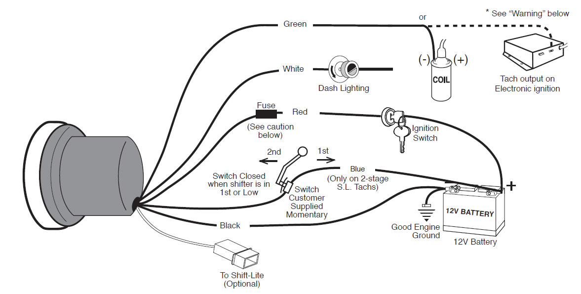
Power Wire (+12V):
This wire provides the tachometer with the necessary operating voltage. It should be connected to a switched 12V source – a circuit that's only active when the ignition is on. Often, this is connected to the ignition coil or a dedicated ignition circuit in the fuse box.
Ground Wire (GND):
This wire provides the return path for the electrical current. It's crucial for proper operation. A solid, clean connection to the chassis is essential. A bad ground can cause erratic readings or prevent the tach from working at all.
Signal Wire (RPM Signal):
This wire receives the signal that represents engine RPM. This is the most crucial wire for accurate readings. The signal source varies depending on your ignition system:
- Conventional Ignition (Points/Distributor): Connected to the negative (-) terminal of the ignition coil.
- Electronic Ignition (HEI, MSD): May connect to the tach output on the ignition control module (ICM) or the negative (-) side of the coil, depending on the ICM design.
- Modern Fuel Injection (EFI/ECU): Taps into the tach output signal from the ECU. This is usually a dedicated wire, often labeled "Tach Output" or "RPM Signal".
- Diesel Engines: Usually picks up the signal from the alternator.
Light Wire (Optional):
Provides power to the internal illumination of the tachometer. Typically connected to the headlight circuit or a dedicated dash light circuit.
Shift Light (Optional):
Some tachometers have a built-in shift light. The wiring for this feature will include connections for power, ground, and a signal wire that triggers the light when the pre-set RPM is reached.
Understanding the Symbols
Wiring diagrams use a standardized set of symbols to represent components and connections. Here's a breakdown of the most common symbols you'll encounter in an Auto Meter tachometer diagram:
- Solid Lines: Represent wires. The thickness of the line typically indicates the gauge (thickness) of the wire.
- Dashed Lines: May indicate a shielded wire or a wire that's part of a harness.
- Circles: Can represent various components, depending on what's inside (e.g., a resistor, capacitor, or diode). Refer to the diagram's legend for specific definitions.
- Ground Symbol: Usually a series of horizontal lines, often resembling an inverted triangle. Indicates a connection to the chassis ground.
- Fuse Symbol: A squiggly line inside a rectangle. Shows the location of a fuse in the circuit.
- Connector Symbol: A series of interlocking shapes. Indicates a plug-and-socket connection.
- Colors: Wires are often color-coded (e.g., red for +12V, black for ground, green for signal). The diagram will usually list the wire colors and their corresponding functions.
Important Note: Auto Meter tachometer diagrams will clearly label each wire and its function. This is the most reliable way to identify the connections, rather than relying solely on color. Wire colors can fade or be changed by previous owners.
How It Works
The tachometer operates by counting the electrical pulses generated by the ignition system (or, in some cases, the ECU or alternator). Each pulse represents a spark event or a rotation of the engine. The tachometer's internal circuitry converts these pulses into a reading that's displayed on the gauge face. Higher RPM means more pulses per minute, resulting in a higher reading on the tachometer.
The power wire provides the necessary voltage for the tachometer's internal circuitry to operate. The ground wire provides the return path for the current. The signal wire transmits the pulses from the ignition system (or ECU/alternator) to the tachometer. The light wire illuminates the gauge face for nighttime visibility. The shift light (if equipped) is triggered when the engine reaches a pre-set RPM, providing a visual cue for the driver to shift gears.
Real-World Use: Basic Troubleshooting Tips
Here's how to troubleshoot common problems using the wiring diagram:
- Tachometer Doesn't Work At All:
- Check the fuse protecting the tachometer circuit.
- Verify that the power wire is receiving +12V when the ignition is on.
- Check the ground connection. Ensure it's clean and securely connected to the chassis. Use a multimeter to verify continuity between the ground wire and the chassis.
- Erratic Readings:
- Check the signal wire connection. Ensure it's securely connected to the correct terminal on the ignition coil, ECU, or alternator.
- A bad ground can also cause erratic readings. Double-check the ground connection.
- Consider the possibility of electrical interference. Shielded signal wires can help reduce interference.
- Dim or Flickering Illumination:
- Check the light wire connection. Ensure it's properly connected to the headlight circuit or dash light circuit.
- Check the bulb inside the tachometer. It may be burned out or loose.
Safety First!
Working with automotive electrical systems can be dangerous. Here are some safety precautions:
- Disconnect the Battery: Always disconnect the negative (-) battery cable before working on any electrical circuits. This prevents accidental shorts and potential damage to the electrical system.
- Be Mindful of the Ignition Coil: The ignition coil can generate high voltage. Avoid touching the coil terminals while the engine is running or the ignition is on.
- Use Proper Tools: Use insulated tools designed for automotive electrical work.
- Consult a Professional: If you're uncomfortable working with electrical systems, consult a qualified mechanic.
Warning: Incorrect wiring can damage the tachometer, the ignition system, or other electrical components. Always double-check your connections before applying power.
We hope this article has provided you with a strong foundation for understanding Auto Meter tachometer wiring diagrams. With this knowledge, you'll be well-equipped to install, troubleshoot, and customize your tachometer with confidence.
We have the Auto Meter tachometer wiring diagram available as a downloadable file. Please contact us if you need assistance to obtain it.