
Automatic Charging Relay Wiring Diagram
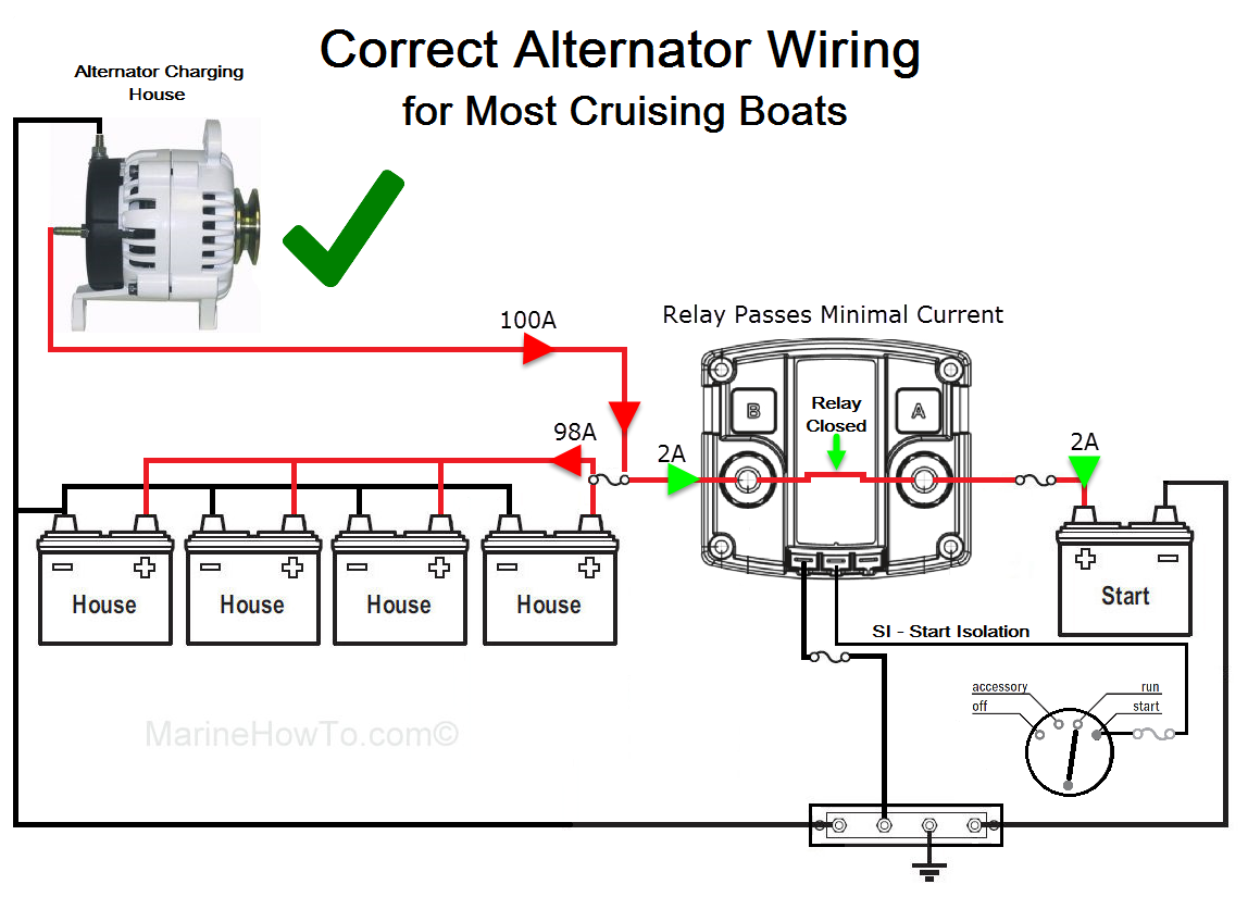
So, you're looking to understand Automatic Charging Relay (ACR) wiring diagrams? Excellent choice. Whether you're adding a dual-battery system to your campervan, boat, or off-road vehicle, knowing how an ACR is wired is crucial for ensuring reliable power and preventing electrical headaches. This guide will break down the typical wiring diagram, explain the components, and give you the knowledge to diagnose issues should they arise. We'll avoid overly simplistic explanations and delve into the technical aspects you need as an experienced DIYer.
Why This Diagram Matters
Understanding the ACR wiring diagram isn't just about connecting wires. It’s about safety, reliability, and maximizing the lifespan of your electrical components. This knowledge is invaluable for:
- Troubleshooting: Quickly identify faults in your charging system.
- DIY Installations: Confidently install or upgrade your dual-battery setup.
- Customization: Adapt the system to your specific needs.
- Understanding System Behavior: Gaining insight into how your batteries are charged and isolated.
- Preventative Maintenance: Catch potential problems before they lead to costly repairs.
Key Specs and Main Parts
Let's identify the key components typically found in an ACR wiring diagram. Understanding their roles is essential for interpreting the diagram.
- Automatic Charging Relay (ACR): The heart of the system. It's an electromechanical or solid-state relay that automatically connects or disconnects two battery banks (house and starting) based on voltage thresholds. Crucially, it protects the starting battery from being drained by auxiliary loads.
- Starting Battery: Dedicated to starting the engine. You want to ensure this one always has enough charge.
- House Battery (Auxiliary Battery): Powers your accessories, lights, appliances, etc. This bank can be deep-cycled (discharged significantly) without damaging it, unlike a starting battery.
- Alternator: The vehicle's primary charging source. It recharges both batteries when the engine is running.
- Fuses or Circuit Breakers: Critical for overcurrent protection. They prevent damage to the wiring and components in case of a short circuit. Always size these appropriately for the wire gauge and load.
- Grounding Points: All components must be properly grounded to the vehicle's chassis for safety and proper operation. A common ground is usually recommended to avoid ground loops.
- Voltage Sensing Wires: Some ACRs require dedicated voltage sensing wires connected directly to the battery terminals. These wires provide accurate voltage readings to the ACR, allowing it to make informed decisions about charging and isolation.
- Manual Override Switch (Optional): Allows manual control of the ACR, forcing it to connect or disconnect the battery banks. This can be useful in emergency situations, such as jump-starting the engine from the house battery.
Typical ACR Specifications:
- Voltage Threshold: The voltage at which the ACR connects or disconnects the battery banks. Common values are around 13.0-13.8V for connection and 12.5-12.8V for disconnection.
- Current Rating: The maximum continuous current the ACR can handle. Choose an ACR with a current rating that exceeds the maximum expected load on the house battery bank. Values vary, but 120A, 140A, 180A are common.
- Operating Voltage: Usually 12V or 24V DC, depending on the vehicle's electrical system.
Decoding the Wiring Diagram: Symbols, Lines, and Colors
Understanding the symbols is key to reading any electrical diagram. Here's a breakdown:
- Solid Lines: Represent wires. The thickness often corresponds to the wire gauge (thicker lines indicate thicker wires).
- Dashed Lines: Often indicate control wires or signal wires that carry low current.
- Colors: Wires are often color-coded. While conventions vary, here are some common ones:
- Red: Positive (+) DC voltage.
- Black: Negative (-) DC voltage (ground).
- Yellow or Blue: Often used for signal wires or accessory circuits.
- Battery Symbol: Two unequal parallel lines, with the longer line representing the positive terminal and the shorter line representing the negative terminal.
- Fuse/Circuit Breaker Symbol: A wavy line within a circle or rectangle.
- Ground Symbol: Several horizontal lines descending in size, often resembling an upside-down pyramid.
- ACR Symbol: Usually a rectangle with terminals labeled for battery connections and control signals. The manufacturer's datasheet will provide the specific pinout.
- Alternator Symbol: Often represented as a circle with the letters "ALT" inside.
- Switch Symbol: A line that can be open or closed to connect or disconnect a circuit.
Note: Always refer to the specific ACR's documentation for its unique wiring diagram and symbol conventions, as they can vary between manufacturers and models.
How It Works: The Charging Dance
Here’s how a typical ACR system operates:
- Engine Off: The ACR is typically open (disconnected) when the engine is off and the voltage of either battery bank is below the connection threshold (e.g., 13.0V). This prevents the house battery from draining the starting battery, ensuring you can always start the vehicle.
- Engine Running: When the engine starts and the alternator begins charging, the voltage of the starting battery rises. Once it reaches the connection threshold, the ACR closes (connects) the two battery banks in parallel.
- Parallel Charging: With the ACR closed, both batteries are charged simultaneously by the alternator. The ACR essentially creates a single, larger battery bank.
- Engine Off (Charging Complete): When the engine is turned off, and the voltage of either battery bank drops below the disconnection threshold (e.g., 12.5V), the ACR opens, isolating the two batteries. The house battery can then be discharged by powering accessories without affecting the starting battery.
Advanced ACRs may incorporate additional features, such as:
- Temperature Compensation: Adjusting the voltage thresholds based on battery temperature for optimal charging.
- Low-Voltage Disconnect (LVD): Automatically disconnecting the house battery from the load when its voltage drops too low, preventing deep discharge and prolonging battery life.
Real-World Use: Basic Troubleshooting Tips
Here are some common issues and troubleshooting steps:
- ACR Not Connecting:
- Check the voltage of the starting battery with the engine running. Is it reaching the connection threshold?
- Verify the ACR's power and ground connections.
- Inspect the voltage sensing wires (if applicable) for damage or loose connections.
- Test the ACR itself. You can usually bypass it manually (if it has a manual override) or use a multimeter to check for continuity across the terminals when it should be closed.
- ACR Not Disconnecting:
- Check the voltage of both battery banks with the engine off. Are they dropping below the disconnection threshold?
- Test the ACR to see if it's stuck in the closed position.
- Look for any external factors keeping the voltage high, such as a solar charger.
- Blown Fuses:
- Identify the cause of the overcurrent. Is there a short circuit? Is the load exceeding the fuse's rating?
- Replace the fuse with one of the same rating. Never use a higher-rated fuse.
- Voltage Drop:
- Check for corroded connections or undersized wiring.
- Ensure all grounding points are clean and secure.
Safety First: Handle with Care
Working with automotive electrical systems can be dangerous. Here are some critical safety precautions:
- Disconnect the Negative Terminal: Before working on any electrical components, disconnect the negative terminal of both batteries to prevent accidental short circuits.
- Wear Safety Glasses: Protect your eyes from sparks or debris.
- Use Insulated Tools: Prevent electric shock.
- Work in a Well-Ventilated Area: Batteries can release flammable gases.
- Avoid Working Alone: Have someone nearby in case of an emergency.
- Capacitors: High current capacitors can store voltage and give a dangerous shock!
Understanding the ACR wiring diagram is a valuable skill for anyone working with dual-battery systems. By grasping the function of each component and following proper safety procedures, you can confidently install, troubleshoot, and maintain your system for years to come.
We have prepared a detailed ACR wiring diagram file as a supplement to this article. Feel free to download it for a more visual and practical guide.