Automatic Transfer Switch Wiring Diagram Pdf
Alright, let's dive into Automatic Transfer Switch (ATS) wiring diagrams. Think of this as the nervous system of your backup power setup. Understanding it is crucial if you're troubleshooting issues, planning modifications, or just want a deeper grasp of how your system operates. We've got a downloadable PDF diagram available – more on that later. For now, let's break down what makes these diagrams tick.
Why This Diagram Matters
Imagine your power goes out during a storm. Your generator kicks in, but how does the power seamlessly switch from the grid to the generator without frying everything? That’s the ATS doing its job, and the wiring diagram is the roadmap to understanding that process. These diagrams are essential for several reasons:
- Troubleshooting: When your ATS isn't working correctly, the diagram helps you pinpoint the exact problem area. Instead of blindly poking around, you can trace circuits and identify faulty components.
- Repairs: Need to replace a relay or rewire a section? The diagram tells you exactly where each wire goes, preventing costly (and potentially dangerous) mistakes.
- System Understanding: Even if everything's working fine, studying the diagram gives you a solid understanding of your system's design and operation. This is invaluable for future upgrades or modifications.
- Safe Modifications: Thinking of adding a load shedding module, or integrating solar? The wiring diagram provides the necessary foundation to ensure your modifications are electrically safe and compatible.
Key Specs and Main Parts of an ATS
An ATS isn't just a single box; it's a system with several key components working in harmony. Knowing these components is essential for interpreting the wiring diagram:
- Main Controller: This is the brains of the operation. It monitors the utility power, senses when it fails, and initiates the transfer to generator power.
- Contactors (or Relays): These are electrically operated switches that physically connect either the utility power or the generator power to your load (your house, business, etc.). They are often heavy-duty to handle significant current. Think of them as very robust remote-controlled light switches.
- Voltage Sensing Circuits: These circuits constantly monitor the voltage on the utility and generator lines. If the utility voltage drops below a certain threshold (usually around 70-80% of nominal voltage), the ATS initiates a transfer.
- Timing Circuits: These introduce delays to prevent nuisance tripping (short power glitches) and to allow the generator to warm up before connecting to the load.
- Wiring Harness: The network of wires connecting all the components. The wiring diagram is your key to understanding this network.
- Neutral and Ground Connections: Critical for safety and proper operation. Incorrect grounding can lead to dangerous voltage potentials and equipment damage.
Understanding the Symbols
ATS wiring diagrams use standardized symbols to represent electrical components. Understanding these symbols is key to deciphering the diagram. Let’s look at some common ones:
- Lines: Solid lines represent conductors (wires). Dashed lines often represent control signals or communication lines. The thickness of the line might indicate the wire gauge (thicker line = larger wire).
- Colors: Colors are used to identify different circuits and functions. Common color codes include:
- Black: Typically used for hot (live) wires in AC circuits.
- White: Typically used for neutral wires in AC circuits.
- Green (or Bare): Always used for ground wires.
- Red: Often used for a second hot wire in 240V circuits, or for control signals.
- Blue/Yellow: Often used for control signals.
- Relays/Contactors: These are usually represented by a coil symbol and a set of contacts. The contacts can be Normally Open (NO) or Normally Closed (NC). NO contacts are open when the relay is not energized and close when it is. NC contacts are closed when the relay is not energized and open when it is.
- Fuses/Circuit Breakers: Represented by a squiggly line inside a rectangle or circle. These are safety devices that protect the circuit from overcurrent.
- Resistors: Represented by a zig-zag line. These limit current flow.
- Capacitors: Represented by two parallel lines. These store electrical energy.
- Transformers: Represented by two coils linked by parallel lines. These change voltage levels.
- Ground: Represented by a series of descending horizontal lines.
Remember, the specific symbols may vary slightly depending on the manufacturer, but they generally adhere to industry standards. The diagram should include a legend explaining any non-standard symbols used.
How It Works: The Switching Process
The magic of the ATS lies in its ability to automatically switch between the utility power and the generator. Here's a simplified breakdown:
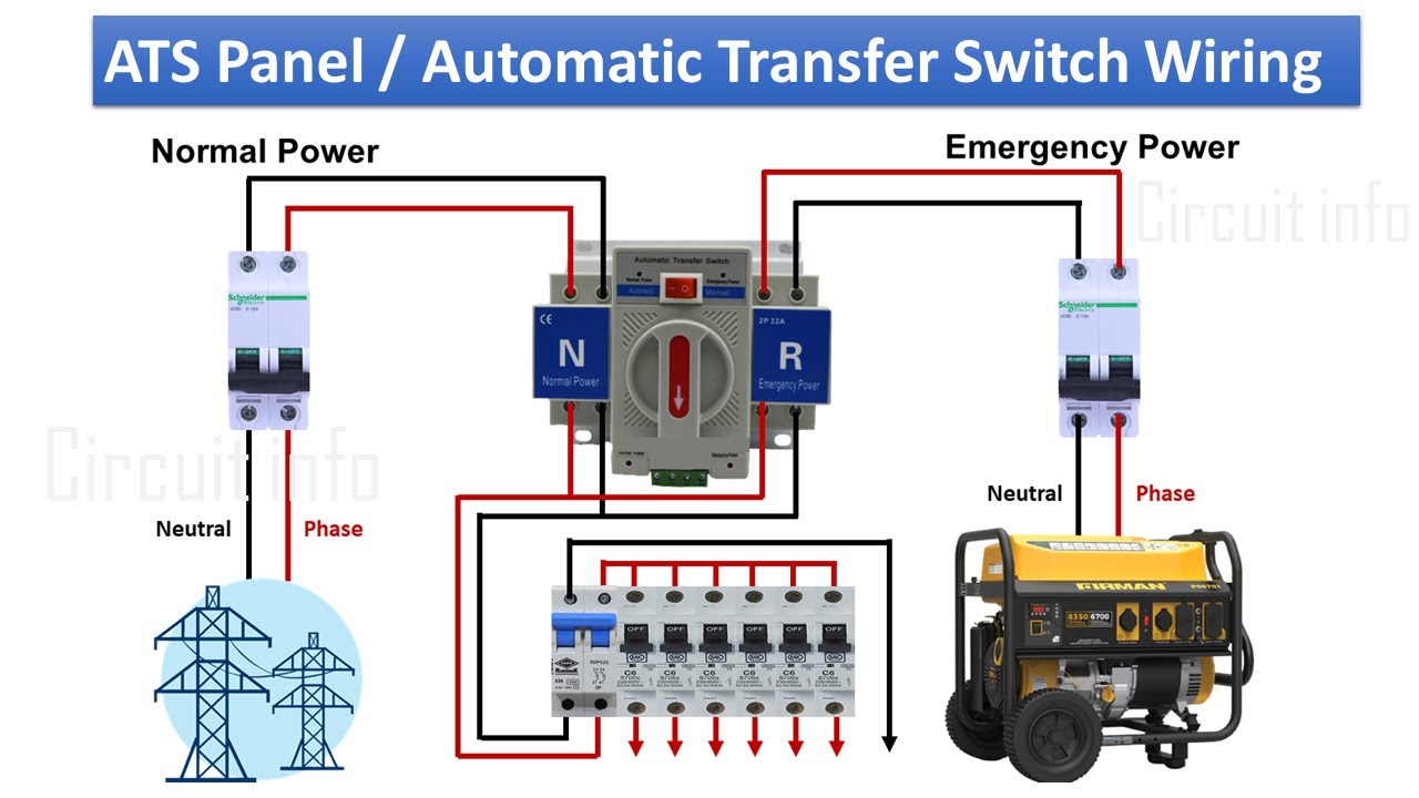
- Normal Operation (Utility Power Present): The ATS continuously monitors the utility power. The contactor for the utility power is closed, supplying power to your load. The generator contactor is open.
- Utility Power Failure: When the utility power fails (voltage drops below the threshold), the ATS controller detects this and initiates the transfer sequence.
- Generator Start: The ATS sends a signal to start the generator.
- Time Delay: A time delay (usually a few seconds) allows the generator to warm up and stabilize its output voltage and frequency.
- Transfer: After the time delay, the ATS opens the utility power contactor and closes the generator power contactor, connecting the generator to your load.
- Utility Power Restoration: When the utility power returns and remains stable for a predetermined time, the ATS initiates the reverse transfer sequence.
- Re-transfer: The ATS opens the generator contactor and closes the utility power contactor, reconnecting your load to the utility power.
- Generator Shutdown: The ATS sends a signal to shut down the generator.
Real-World Use: Basic Troubleshooting
Let's say your generator starts when the power goes out, but your house doesn't get power. Here's how the wiring diagram can help:
- Check the Generator Contactor: Use the diagram to locate the generator contactor. With the generator running, check if voltage is present on both sides of the contactor. If voltage is present on the generator side but not on the load side, the contactor is likely faulty.
- Inspect Control Wiring: The diagram will show you the control wiring for the contactors. Check for loose connections or damaged wires. A broken wire in the control circuit could prevent the contactor from closing.
- Verify Voltage Sensing Circuits: Use a multimeter to check the voltage at the voltage sensing circuits on both the utility and generator sides. The readings should be within the expected range. If not, there may be a problem with the sensing circuit.
- Look for Blown Fuses: The diagram will show the location of all fuses. Use a multimeter to check for continuity across each fuse. A blown fuse indicates an overcurrent condition that needs to be investigated.
Safety First: Risky Components
Working with electricity is inherently dangerous. Here are some specific safety considerations when working with ATS systems:
- High Voltage: ATS systems deal with high voltage (120V/240V or higher). Always disconnect the power supply before working on the system. Double-check with a multimeter to ensure the power is off.
- Capacitors: Capacitors can store a dangerous electrical charge even after the power is disconnected. Discharge capacitors before touching them.
- Moving Parts: The contactors have moving parts that can pinch or crush fingers. Keep your hands clear when the system is energized.
- Grounding: Proper grounding is critical for safety. Ensure that the ATS is properly grounded according to the manufacturer's instructions and local electrical codes. Improper grounding can be lethal.
- Lockout/Tagout: When working on the system, use lockout/tagout procedures to prevent accidental energization. This involves disconnecting the power source and placing a lock and tag on the disconnect switch to prevent anyone from turning it back on while you're working.
If you're not comfortable working with electricity, it's best to consult a qualified electrician.
We understand that tackling electrical projects can be daunting, but with the right knowledge and precautions, you can gain a solid understanding of your ATS system. As promised, we have a downloadable PDF wiring diagram available. This diagram is a general example but provides a good starting point for understanding the principles. You'll want to consult the specific diagram for *your* ATS model for accurate information. Understanding the theory is key to interpreting all diagrams.
Happy wiring (safely)!