Autometer Shift Light Wiring Diagram
So, you're thinking about adding a shift light to your ride, or maybe you're troubleshooting one that's acting up? Good call. A shift light is a fantastic way to improve your performance on the track (or just add some visual flair) by giving you a clear, immediate indication of when to shift. But before you start splicing wires, you need to understand the wiring diagram. This article will break down the Autometer shift light wiring diagram, explain what each component does, and give you some troubleshooting tips to ensure your installation goes smoothly. Think of this as your comprehensive guide to illuminating your shifting game.
Purpose: Decoding the Map to Redline
Why bother understanding the wiring diagram? Simple: knowledge is power. A shift light wiring diagram isn't just a pretty picture; it's the roadmap to a successful installation and a reliable system. Whether you're installing a new shift light, diagnosing a problem with an existing one, or simply trying to understand how it all works, the diagram is your key. Attempting to install or repair without a proper understanding of the wiring can lead to damage to your vehicle's electrical system, the shift light itself, or worse, injury.
Key Specs and Main Parts
Let's identify the critical components and their essential specifications. Most Autometer shift lights, and really most shift lights in general, share some common elements:
- Shift Light Unit: This is the visible part, the LED or incandescent bulb that lights up. Its specification is usually based on the light's intensity (brightness) and color. LED shift lights are preferred for their longevity and brightness.
- Control Box (if applicable): Some shift lights have a separate control box, often used for more advanced features like RPM adjustment and light intensity settings. These boxes contain the electronics to process the tachometer signal and trigger the light.
- Wiring Harness: This is the bundle of wires that connects all the components. Wire gauge (thickness) is an important specification; typically, 18-22 gauge wire is sufficient for most shift light applications, but higher power systems may require thicker gauge wire (lower numerical value = thicker wire).
- RPM Input Wire: This wire connects to the vehicle's tachometer signal. The tachometer is what tells your car’s computer how fast the engine is spinning in revolutions per minute. This is crucial because it's what tells the shift light when to activate.
- Power Wire (Typically +12V): This wire connects to a fused 12-volt power source in your vehicle. Ensure the fuse rating is appropriate for the shift light's power consumption (usually indicated in the shift light's documentation).
- Ground Wire: This wire connects to a solid ground point on the vehicle's chassis. A good ground is essential for proper operation.
Symbols: Reading the Electrical Language
Understanding the symbols used in a wiring diagram is crucial for interpreting the information it conveys. Here's a breakdown of common symbols you'll encounter:
- Solid Lines: Represent wires. The thickness of the line sometimes indicates the wire gauge.
- Dashed Lines: Often represent shielded wires or less critical connections.
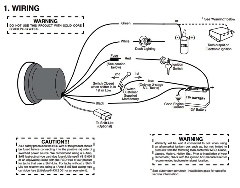
- Color Codes: Wires are typically color-coded (e.g., red for +12V, black for ground, green for tachometer signal). The diagram will usually have a legend indicating what each color represents.
- Circles: Can represent connections or components, depending on the context.
- Resistors (Zigzag Line): Limit current flow.
- Capacitors (Two Parallel Lines): Store electrical energy.
- Diodes (Triangle with a Line): Allow current to flow in one direction only.
- Ground Symbol (Stacked Horizontal Lines or Inverted Triangle): Indicates a connection to the vehicle's chassis ground.
- Fuse Symbol (S-Shaped Line Inside a Rectangle): Indicates a fuse, which protects the circuit from overcurrent.
Pay close attention to the color coding; never assume the color is arbitrary. Using the wrong wire can have catastrophic results. The wiring diagram will define what each wire color is and what it is used for.
How It Works: From RPM to Illumination
The shift light's operation is relatively simple, but the underlying electronics can be complex. Here's the basic process:
- RPM Signal Acquisition: The shift light's RPM input wire taps into the vehicle's tachometer signal. This signal is a series of pulses that correspond to the engine's RPM. The frequency of these pulses increases as the engine speed increases.
- Signal Processing: The shift light's control box (or internal circuitry in simpler models) processes the RPM signal. It filters out noise and converts the pulse frequency into an RPM value.
- Threshold Comparison: The control box compares the calculated RPM value to a pre-set RPM threshold. This threshold is the RPM at which you want the shift light to activate. Many shift lights allow you to adjust this threshold.
- Activation: When the RPM value reaches or exceeds the threshold, the control box sends a signal to the shift light (LED or bulb) to illuminate.
- Deactivation: When the RPM value drops below the threshold, the shift light is deactivated.
Real-World Use: Troubleshooting Tips
Here are some basic troubleshooting tips if your shift light isn't working correctly:
- No Light At All:
- Check the fuse: A blown fuse is the most common cause of a non-functioning shift light.
- Verify power and ground connections: Use a multimeter to ensure you have 12V at the power wire and a good ground connection.
- Inspect the bulb or LED: If it's a traditional bulb, it may be burned out. LEDs can also fail.
- Check the wiring harness for damage: Look for any frayed wires or loose connections.
- Light Stays On All the Time:
- Check the RPM input wire: Ensure it's not shorted to ground.
- Verify the RPM threshold setting: It may be set too low.
- Inspect the control box (if applicable): It may be faulty.
- Light Flickers or Is Erratic:
- Check the ground connection: A poor ground can cause erratic behavior.
- Inspect the RPM input wire for interference: Run it away from high-voltage components like ignition coils.
- The wire could be damaged.
- Light Comes On Too Early or Too Late:
- Adjust the RPM threshold setting: This is the most likely cause.
- Ensure the tachometer signal is accurate: Compare the shift light's reading to your vehicle's tachometer.
Safety: Handling Electrical Components
Working with automotive electrical systems can be dangerous. Here are some essential safety precautions:
- Disconnect the Battery: Before working on any electrical components, disconnect the negative (-) terminal of your vehicle's battery. This will prevent accidental shorts and electrical shocks.
- Use a Multimeter: A multimeter is an essential tool for troubleshooting electrical problems. Use it to check voltage, current, and resistance.
- Wear Safety Glasses: Protect your eyes from sparks and debris.
- Work in a Well-Ventilated Area: Some automotive chemicals can be harmful if inhaled.
- Never Work Alone: It's always a good idea to have someone nearby in case of an emergency.
- Be Careful with Hot Wires: Identifying wires that are constantly “hot” with a multimeter is an important step to not damaging the shift light.
High voltage components such as the ignition system can deliver a harmful, or even fatal, electrical shock. Be certain the ignition is off and the battery is disconnected before working near these components.
Understanding the Autometer shift light wiring diagram is key to successful installation and troubleshooting. Take your time, follow the diagram carefully, and prioritize safety. With a little knowledge and patience, you'll have your shift light working perfectly in no time.
To further assist you with your project, we have a general Autometer Shift Light Wiring Diagram available for download. This diagram provides a visual aid and detailed information to help you understand the wiring process and connections. Please note that specific diagrams may vary depending on your exact Autometer model, but this will serve as a great starting point.