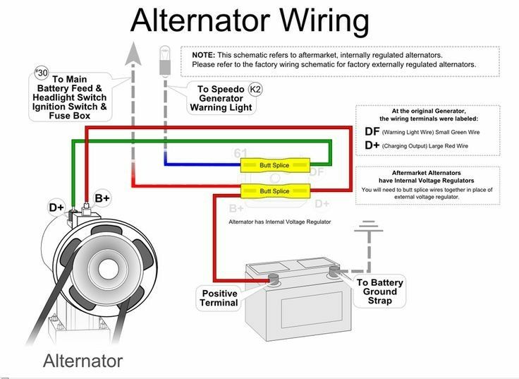
Automobile Alternator Wiring Diagram
So, you're diving into the world of automobile alternators. Good on you! Whether you're chasing down a charging issue, planning an electrical upgrade, or just hungry to understand how your car works, understanding the alternator wiring diagram is key. Think of it as the roadmap to your car's electrical heart. This article will give you the knowledge you need to read, understand, and even troubleshoot using that roadmap.
Purpose of the Alternator Wiring Diagram
Why even bother with these diagrams? Simple: without it, you're flying blind. The alternator wiring diagram is your go-to guide for:
- Troubleshooting Charging Problems: Is your battery constantly dying? The diagram helps you trace the source of the problem, whether it's a bad wire, a faulty regulator, or a completely shot alternator.
- Performing Repairs: Replacing the alternator itself is straightforward, but what if a connector is damaged or a wire is frayed? The diagram shows you how everything connects.
- Wiring Upgrades and Modifications: Adding a high-power audio system, auxiliary lights, or other electrical accessories requires you to understand how much load the alternator can handle and how to properly connect new components. The diagram helps you tap into the system safely and effectively.
- General Electrical System Understanding: Simply put, knowing how the alternator fits into the overall charging system gives you a deeper understanding of your vehicle.
Key Specs and Main Parts Shown on the Diagram
Before we dive into interpreting the lines and symbols, let's get familiar with the main players and their specifications. A typical alternator wiring diagram will highlight these components:
- Alternator: The heart of the charging system. It converts mechanical energy from the engine into electrical energy. Key specs include its voltage rating (typically 12V or 24V in heavy-duty applications) and its amperage output (e.g., 60A, 100A, 150A). Amperage indicates how much current the alternator can deliver.
- Battery: The energy reservoir. It stores electrical energy and provides it to start the engine and power accessories when the engine isn't running. Its voltage rating (typically 12V) and cold cranking amps (CCA) are important specifications.
- Voltage Regulator: This crucial component controls the alternator's output voltage to prevent overcharging the battery. It's either internal (built into the alternator) or external (mounted separately). The diagram will show its connection to the alternator and battery.
- Ignition Switch: This controls the flow of power to the alternator's field circuit, turning it on and off with the engine. The diagram will show which terminals of the switch are involved.
- Fuses and Fusible Links: Safety devices that protect the electrical system from overloads and short circuits. The diagram shows their location and amperage rating.
- Wiring Harness: The network of wires that connect all the components. Wire gauge (thickness) is an important specification, as it determines how much current the wire can safely carry.
- Ground Connection(s): Essential for completing the electrical circuit. A good, clean ground is critical for proper alternator operation. The diagram will show where the alternator and other components are grounded to the vehicle's chassis or engine block.
Decoding the Symbols: Lines, Colors, and Icons
Understanding the symbols on an alternator wiring diagram is like learning a new language. Here's a breakdown of the common elements:
- Lines:
- Solid Lines: Represent wires. The thickness of the line doesn't necessarily indicate wire gauge, so always refer to the wire specification if it's listed.
- Dashed Lines: May indicate shielded wires or wires that are part of a harness.
- Arrows: Indicate the direction of current flow (conventional current flow, from positive to negative, is generally used).
- Colors: Wire colors are crucial for identifying the correct wire in the harness. Common colors include:
- Red: Typically used for battery power (B+).
- Black: Typically used for ground.
- Yellow: Often used for ignition-switched power.
- Blue, Green, White: Used for various control signals and accessories.
- Icons:
- Alternator: Usually represented by a circle with the letters "ALT" or "GEN" inside.
- Battery: Represented by a series of long and short parallel lines, indicating the positive and negative terminals.
- Voltage Regulator: Shown as a rectangle or square with the letters "VR" inside.
- Fuses: Represented by a zigzag line inside a rectangle or circle. The amperage rating is usually indicated next to the symbol.
- Relays: Shown as a coil and a switch.
- Ground: Represented by a series of horizontal lines decreasing in length, often resembling a Christmas tree.
How the Alternator Charging System Works
The alternator charging system is a relatively simple yet ingenious setup. Here's the basic flow:
- When you turn the ignition key, power is supplied to the voltage regulator and the alternator's field winding (also called the rotor). This creates a magnetic field inside the alternator.
- As the engine starts and the alternator pulley spins, this magnetic field rotates past the stator windings (stationary coils of wire).
- This rotating magnetic field induces an alternating current (AC) in the stator windings.
- The alternator's rectifier (a set of diodes) converts the AC current to direct current (DC), which is what the car's electrical system uses.
- The voltage regulator monitors the battery voltage and adjusts the amount of current flowing through the field winding. This controls the strength of the magnetic field and, therefore, the alternator's output voltage. If the battery voltage is low, the regulator increases the field current, increasing the alternator's output. If the battery is fully charged, the regulator decreases the field current, reducing the alternator's output.
- The DC current from the alternator charges the battery and powers the vehicle's electrical accessories.
Real-World Use: Basic Troubleshooting Tips
Okay, let's put this knowledge to work. Here are some common alternator-related problems and how the wiring diagram can help:
- Battery Not Charging:
- Check the alternator's B+ terminal: Use a voltmeter to check the voltage at the alternator's B+ terminal with the engine running. It should be around 13.5-14.5V. If it's significantly lower, the alternator may be faulty or not receiving proper excitation voltage (voltage from the ignition switch that tells the alternator to start charging). Use the wiring diagram to trace the B+ wire back to the battery and check for voltage drops along the way.
- Check the field circuit: Use the wiring diagram to identify the field circuit wire. With the ignition on but the engine off, check for voltage at this wire. If there's no voltage, the ignition switch or wiring to the regulator may be faulty.
- Check the ground connection: A poor ground connection can cause all sorts of problems. Use the wiring diagram to locate the alternator's ground connection and ensure it's clean and tight.
- Overcharging:
- Check the voltage regulator: Overcharging is usually caused by a faulty voltage regulator. If the wiring diagram shows an external voltage regulator, you can test it separately. If the regulator is internal, the entire alternator likely needs to be replaced.
- Alternator Light on Dashboard:
- Consult the wiring diagram: The alternator light circuit usually includes a wire that connects to the alternator. If the alternator isn't charging properly, this wire will ground, turning on the light. Use the diagram to trace this wire and identify any potential faults.
Safety First: Risky Components
Working with automotive electrical systems can be dangerous. Keep these safety precautions in mind:
- Disconnect the Battery: Before working on any electrical component, disconnect the negative (-) battery cable to prevent short circuits and electrical shocks.
- Avoid Short Circuits: Be extremely careful not to short circuit any wires to ground. This can damage components and even start a fire.
- Handle Capacitors with Care: Some alternators contain capacitors that can store a charge even after the battery is disconnected. Allow time for these to discharge or use a resistor to safely discharge them before touching them.
- High Voltage: While the nominal voltage is 12V, the alternator can generate much higher voltages internally. Avoid touching any exposed terminals or wires while the engine is running.
With a solid understanding of your alternator wiring diagram, you'll be much better equipped to diagnose and repair charging system problems, perform electrical upgrades, and generally keep your vehicle running smoothly. Remember to always consult your specific vehicle's repair manual for the most accurate and up-to-date information.
We have a typical alternator wiring diagram available for download. Use it as a reference while learning about alternator wiring.