Automotive Air Conditioning System Diagram
Automotive air conditioning (A/C) systems can seem like a black box, but understanding their inner workings – depicted in a system diagram – is invaluable for anyone tackling repairs, modifications, or simply wanting a deeper knowledge of their vehicle. This article will break down the A/C system diagram, explaining its purpose, components, functionality, and how to use it for troubleshooting.
Purpose of an Automotive A/C System Diagram
An A/C system diagram is a roadmap of the entire cooling system. It visually represents all the components, their connections, and the flow of refrigerant throughout the system. This diagram serves several critical purposes:
- Troubleshooting: By tracing the refrigerant path, you can identify potential leak points, component failures, or blockages.
- Repair: The diagram aids in locating specific parts and understanding how they integrate into the system, simplifying repairs and replacements.
- Modification: If you're considering upgrading or modifying your A/C system (e.g., installing a larger condenser), the diagram helps you understand the existing setup and plan your changes effectively.
- Education: It's an excellent tool for learning about how the A/C system functions, even if you're not planning any immediate work.
Without a diagram, you're essentially working blind. With it, you can approach A/C issues methodically and confidently.
Key Specs and Main Parts
Before diving into the diagram itself, let's review the main components of a typical automotive A/C system:
- Compressor: The heart of the system, the compressor pressurizes the refrigerant, increasing its temperature. It's driven by the engine via a belt. Key spec: Displacement (cc) - indicates the volume of refrigerant it can compress per revolution.
- Condenser: A radiator-like component located in front of the engine radiator. The hot, high-pressure refrigerant releases heat to the atmosphere, condensing into a high-pressure liquid. Key spec: Surface area (square inches) - affects heat dissipation capacity.
- Receiver-Drier (or Accumulator): This component filters out moisture and debris from the refrigerant and stores excess liquid refrigerant. Receiver-driers are typically used with expansion valve systems, while accumulators are used with orifice tube systems. Key spec: Desiccant type and capacity - determines its moisture-absorbing ability.
- Expansion Valve (or Orifice Tube): This metering device controls the flow of refrigerant into the evaporator, causing a pressure drop and allowing the refrigerant to expand and cool. Expansion valves are more sophisticated and offer better temperature control than orifice tubes. Key spec: Flow rate (pounds per hour) - dictates the amount of refrigerant that can be metered.
- Evaporator: Located inside the passenger compartment, the evaporator absorbs heat from the cabin air, cooling the air that blows into the vehicle. The refrigerant evaporates into a low-pressure gas. Key spec: Surface area (square inches) - affects heat absorption capacity.
- Refrigerant Lines: Hoses and pipes that connect all the components and carry the refrigerant. These lines must be specifically designed to withstand the high pressures and temperatures of the A/C system. Key spec: Material (e.g., barrier hose) - indicates refrigerant permeability.
- Pressure Switches: These switches monitor refrigerant pressure and protect the system from damage due to over- or under-pressure. They can shut off the compressor or activate warning lights. Key spec: Pressure settings (PSI) - determine the activation/deactivation thresholds.
- Service Ports: These ports allow technicians to connect gauges and equipment for charging, evacuating, and testing the system.
Symbols and Legend
Understanding the symbols used in the A/C diagram is crucial for interpreting it correctly. While symbols can vary slightly between manufacturers, here are some common conventions:
- Lines:
- Solid Lines: Typically represent refrigerant lines.
- Dotted Lines: Often indicate electrical wiring.
- Thick Lines: Can signify high-pressure lines.
- Thin Lines: May represent low-pressure lines or control signals.
- Colors:
- Red: Commonly used for high-pressure liquid refrigerant.
- Blue: Frequently indicates low-pressure gas refrigerant.
- Green: Might represent refrigerant in a mixed state (liquid/gas).
- Black: Typically used for electrical grounds.
- Icons:
- Compressor: Usually depicted as a pump-like symbol.
- Condenser: Often represented as a radiator-like symbol with wavy lines indicating heat dissipation.
- Receiver-Drier/Accumulator: A cylindrical shape with desiccant symbols (e.g., a small bag or dots).
- Expansion Valve/Orifice Tube: A restriction symbol, often a narrowing of the refrigerant line.
- Evaporator: Similar to the condenser, but located inside the passenger compartment.
- Pressure Switches: A switch symbol with pressure readings.
- Service Ports: Usually indicated by a capped fitting symbol.
Always refer to the legend on the specific diagram you're using, as these conventions can vary.
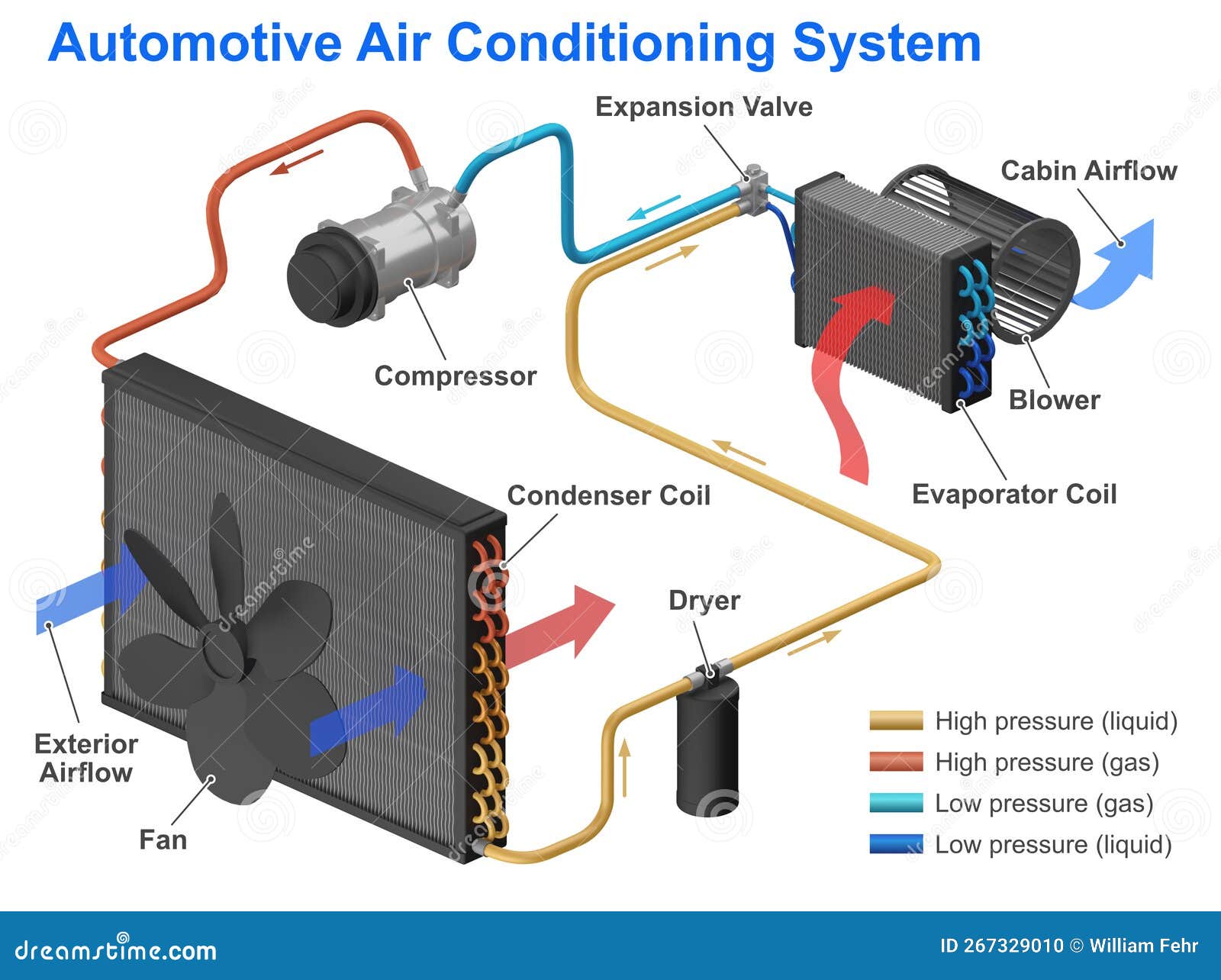
How It Works: The Refrigeration Cycle
The A/C system operates on the principle of the refrigeration cycle. Here's a simplified explanation:
- Compression: The compressor compresses the low-pressure, low-temperature refrigerant gas into a high-pressure, high-temperature gas.
- Condensation: The hot, high-pressure refrigerant gas flows to the condenser, where it releases heat to the atmosphere and condenses into a high-pressure, high-temperature liquid.
- Metering: The high-pressure liquid refrigerant flows through the receiver-drier (to remove moisture and debris) and then to the expansion valve or orifice tube. The expansion valve or orifice tube restricts the flow, creating a pressure drop.
- Evaporation: As the refrigerant enters the evaporator, the pressure drop causes it to expand and evaporate into a low-pressure, low-temperature gas. This evaporation process absorbs heat from the air flowing across the evaporator coil, cooling the cabin air.
- Return: The low-pressure, low-temperature refrigerant gas returns to the compressor, completing the cycle.
Real-World Use: Basic Troubleshooting
The A/C diagram is your best friend when troubleshooting. Here are a few common issues and how the diagram can help:
- No Cooling:
- Check for a blown fuse or tripped relay using the electrical portion of the diagram.
- Verify compressor clutch engagement (listen for a click when the A/C is turned on). The diagram shows the wiring to the compressor clutch.
- Look for obvious leaks in refrigerant lines, the condenser, or the evaporator. The diagram helps you locate these components.
- Poor Cooling:
- Check refrigerant levels. Service ports, indicated on the diagram, allow for gauge connections.
- Inspect the condenser for debris blockage. The diagram shows its location in front of the radiator.
- Ensure the expansion valve or orifice tube is functioning correctly. The diagram helps you pinpoint its location.
- Strange Noises:
- Identify potential sources of noise by tracing the system components on the diagram. A noisy compressor is a common culprit.
Remember that A/C troubleshooting often requires specialized tools and knowledge. If you're not comfortable, consult a professional.
Safety Precautions
Working with A/C systems involves potential hazards:
- Refrigerant: Refrigerant is a chemical that can cause frostbite and respiratory irritation. Always wear appropriate personal protective equipment (PPE), including gloves and eye protection. Never release refrigerant into the atmosphere. It's harmful to the environment and illegal in many places.
- High Pressure: A/C systems operate at high pressures. Never disconnect lines or components without properly discharging the system. Improperly disconnecting a pressurized line can cause serious injury.
- Electrical Components: Be aware of electrical components like the compressor clutch and pressure switches. Disconnect the battery before working on electrical connections.
Always follow safety procedures and consult a qualified technician if you are unsure about any aspect of A/C system repair.
Having access to the complete A/C system diagram for your specific vehicle is incredibly valuable. We have a general A/C system diagram available for download to help you get started, but be sure to consult your vehicle's service manual for the most accurate and detailed information for your specific make and model.