Automotive Alternator Wiring Diagram
Understanding your automotive alternator wiring diagram is crucial for various reasons, ranging from performing routine maintenance to diagnosing complex electrical issues. Whether you're troubleshooting a charging problem, upgrading your electrical system for aftermarket accessories, or simply deepening your understanding of automotive electrics, knowing how to read and interpret this diagram empowers you to confidently tackle electrical tasks. This article will guide you through the essential elements of an alternator wiring diagram, providing you with the knowledge to effectively use it.
Key Specs and Main Parts
Before diving into the diagram itself, let's review the key components of an automotive alternator and their associated specifications. Understanding these elements will make the diagram much easier to decipher.
- Alternator Housing: The physical enclosure protecting the internal components.
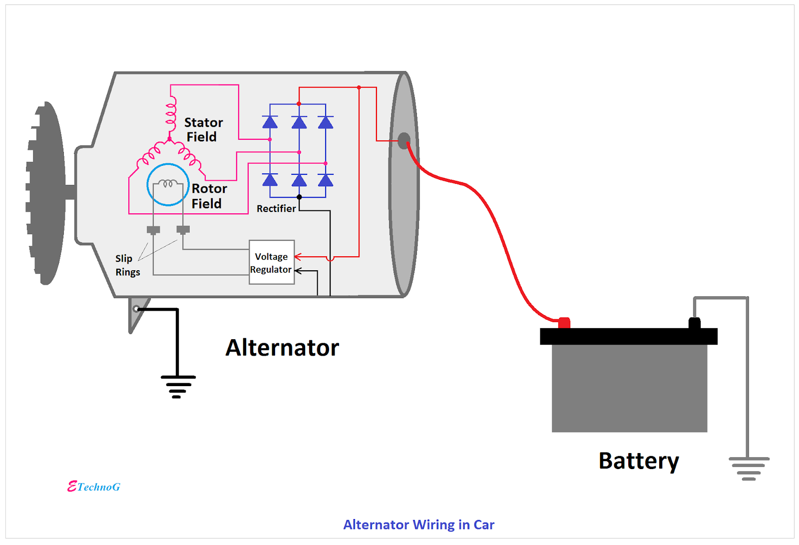
- Stator: The stationary part of the alternator containing windings where AC voltage is induced. Specification often includes number of phases (typically 3) and voltage rating.
- Rotor (or Armature): The rotating part containing the field winding. Current is passed through the rotor via slip rings.
- Regulator: Controls the output voltage of the alternator by varying the current supplied to the rotor. This is a critical component for preventing overcharging. Regulators can be internal or external.
- Rectifier (Diode Bridge): Converts the AC voltage generated by the stator into DC voltage suitable for the car's electrical system. Typically consists of six diodes.
- Slip Rings: Conduct electrical current to the rotating rotor.
- Brushes: Make contact with the slip rings to transfer current to the rotor. These are wear items and often the cause of alternator failure.
- Voltage Output: Typically 13.8 - 14.4 volts in a healthy charging system.
- Current Output: Measured in Amperes (A), varying greatly depending on the vehicle and alternator model. A small car might have an alternator rated for 60A, while a larger vehicle with many electrical accessories could require 150A or more.
- Pulley: Driven by the engine's accessory belt, providing mechanical power to rotate the rotor.
Symbols and Legend
The wiring diagram is a symbolic representation of the electrical circuit. Understanding these symbols is essential for accurate interpretation. Here are some common symbols you'll encounter:
- Solid Lines: Indicate wires carrying electrical current. The thickness of the line *sometimes* (but not always) indicates the wire gauge (thicker line = larger gauge = higher current carrying capacity).
- Dashed Lines: Often represent wires that are optional or present only in specific configurations.
- Arrows: Show the direction of current flow (conventional current, from positive to negative).
- Circles: Represent connections or splices where multiple wires join.
- Rectangles: Represent components such as the regulator, diode bridge, or other electronic modules.
- Ground Symbol: A series of downward-pointing lines indicates a connection to the vehicle's chassis, providing a return path for the current.
- Battery Symbol: Shows the battery, usually with a "+" and "-" indicating polarity.
- Switch Symbol: Shows a switch, which can be open (circuit broken) or closed (circuit complete).
- Fuse Symbol: Represents a fuse, a safety device that protects the circuit from overcurrent.
- Colors: Wiring diagrams use color codes to differentiate wires. Common colors include red (power), black (ground), blue, green, yellow, and white. The legend will define what each color represents in *that specific diagram*. Do NOT assume a color always means the same thing.
Every wiring diagram should include a legend that explains the symbols, abbreviations, and color codes used. Always refer to the legend for the specific diagram you are working with.
How It Works
The alternator's function is to convert mechanical energy from the engine into electrical energy to charge the battery and power the vehicle's electrical system when the engine is running. Here's a simplified explanation of how it works, tied to the wiring diagram:
- Engine Power: The engine's accessory belt drives the alternator's pulley, rotating the rotor.
- Rotor Excitation: The battery provides a small amount of current to the rotor winding (field winding) through the ignition switch. This current is regulated by the voltage regulator. The wiring diagram will show this "exciter" wire, typically connected to the "IG" or "IGN" terminal on the alternator.
- Magnetic Field Generation: The current flowing through the rotor's winding creates a magnetic field.
- AC Voltage Induction: As the rotor spins, its magnetic field cuts across the stator windings, inducing an alternating current (AC) voltage in the stator windings.
- Rectification: The AC voltage from the stator is fed into the diode bridge rectifier, which converts it into direct current (DC) voltage. The wiring diagram will show the three stator winding connections (often labeled "W," "Y," and "B" or similar) leading to the diode bridge.
- Voltage Regulation: The voltage regulator monitors the system voltage and adjusts the current supplied to the rotor winding to maintain a stable output voltage (typically around 14V). If the voltage is too low, the regulator increases the current to the rotor, strengthening the magnetic field and increasing the output voltage. If the voltage is too high, the regulator reduces the current to the rotor.
- DC Output: The DC voltage from the rectifier is then output to the battery and the vehicle's electrical system. This is typically connected to the battery positive terminal via a heavy gauge wire. The wiring diagram will show this heavy gauge wire connected to the "B+" or "BAT" terminal on the alternator.
Real-World Use: Basic Troubleshooting Tips
Here are some basic troubleshooting steps you can perform using the wiring diagram:
- No Charging: If the battery isn't charging, start by checking the "exciter" wire (IG or IGN) for voltage with the ignition on. If there's no voltage, trace the wire back to the ignition switch and identify any breaks or shorts.
- Overcharging: If the battery is overcharging (voltage above 14.5V), suspect a faulty voltage regulator. Check the regulator's wiring connections for corrosion or damage. In some cases, a faulty ground connection can cause overcharging.
- Voltage Drop: Measure the voltage drop across the main charging wire (B+ or BAT) from the alternator to the battery. A high voltage drop indicates a corroded connection or damaged wire.
- Continuity Testing: Use a multimeter to check the continuity of wires between components. This can help identify broken wires or faulty connections. Refer to the wiring diagram to identify the correct wires to test.
- Fuse Checks: Consult the wiring diagram to locate the fuse protecting the alternator circuit. Check the fuse for continuity. A blown fuse indicates a short circuit somewhere in the system.
Safety
Working with automotive electrical systems can be dangerous. Here are some safety precautions to follow:
- Disconnect the Battery: Always disconnect the negative battery cable before working on the electrical system to prevent short circuits.
- Use Proper Tools: Use insulated tools to prevent electrical shock.
- Avoid Water: Never work on the electrical system in wet conditions.
- Be Careful Around the Alternator: The alternator's output voltage can be high enough to cause a shock. Avoid touching the terminals while the engine is running.
- Heavy Gauge Wires: Be especially careful with the main charging wire (B+ or BAT). This wire carries a large amount of current, and a short circuit can cause a fire. Always disconnect the battery before working on this wire.
- Capacitors: Be aware that some circuits contain capacitors, which can store a charge even after the battery is disconnected. Discharge capacitors before working on those circuits.
This information provides a foundation for understanding automotive alternator wiring diagrams. Remember to always consult the specific wiring diagram for your vehicle and exercise caution when working with electrical systems.
We have a sample automotive alternator wiring diagram file available for you to download. This file will allow you to examine a typical diagram in more detail and practice applying the concepts discussed in this article.