
Automotive Electric Fan Wiring Diagram
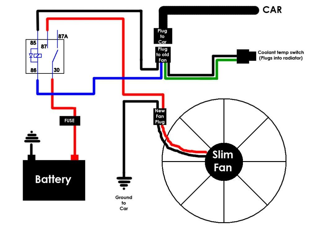
So, you're looking to understand automotive electric fan wiring diagrams? Excellent! Whether you're troubleshooting a cooling issue, upgrading your existing fan setup, or simply want to deepen your understanding of automotive electrical systems, this guide will walk you through the ins and outs. We’ll break down the diagrams, explain the components, and provide some practical tips. Plus, we have a detailed diagram available for download (link at the end!).
Purpose: Why Understand Electric Fan Wiring?
A solid understanding of electric fan wiring is crucial for several reasons:
- Troubleshooting: Diagnosing a malfunctioning electric fan can be tricky without knowing where to start. A wiring diagram gives you a roadmap for tracing the electrical path and identifying the source of the problem.
- Upgrades and Modifications: Swapping a mechanical fan for an electric one (or upgrading to a higher-performing electric fan) often requires custom wiring. A diagram helps you plan and execute the modification safely and effectively.
- Performance Tuning: Electric fans can free up horsepower and improve fuel economy compared to engine-driven mechanical fans. Understanding the wiring lets you optimize the fan's operation for performance.
- Educational Purposes: Even if you don't plan on doing any work yourself, understanding the basics of automotive electrical systems can empower you to make informed decisions about your vehicle’s maintenance and repair.
Key Specs and Main Parts of an Electric Fan Circuit
Before diving into the diagram, let's familiarize ourselves with the key components and their specifications. These typically include:
- Electric Fan Motor: The heart of the system. Typically a 12V DC motor with varying amperage draw depending on the fan's size and power. Expect anywhere from 10 to 30 amps.
- Relay: An electrically operated switch. Used to control the high-current fan motor with a low-current signal. Relays are typically rated for 30-40 amps. This is a crucial safety component.
- Fuse: A safety device designed to protect the circuit from overcurrent. It contains a thin wire that melts and breaks the circuit if the current exceeds its rating. The fuse rating should be slightly higher than the fan's typical operating current (e.g., a 20A fan might use a 25A or 30A fuse).
- Temperature Sensor/Switch: This device monitors the engine coolant temperature and activates the fan when a certain threshold is reached. Different types exist, from simple on/off switches to more sophisticated variable resistance sensors used with an ECU. Common temperature settings range from 180-210°F (82-99°C).
- Wiring Harness: A bundle of wires that connects all the components. The wire gauge (thickness) is critical for handling the current. Use appropriately sized wiring to prevent voltage drop and overheating. Typically, 12-14 gauge wire is used for the fan motor.
- Ground Connection: A secure connection to the vehicle's chassis, providing a return path for the current. A clean and reliable ground is essential for proper operation.
- ECU (Engine Control Unit) - Optional: In some modern vehicles, the electric fan is controlled directly by the ECU, allowing for more sophisticated temperature management and integration with other engine functions.
Symbols and Conventions in Wiring Diagrams
Understanding the symbols used in automotive wiring diagrams is key to interpreting them correctly. Here's a breakdown of common symbols:
- Solid Lines: Represent wires. The thickness of the line doesn't necessarily indicate wire gauge.
- Dashed Lines: Often represent ground connections or shielded wires.
- Circles: Represent components like sensors, switches, and lights.
- Rectangles: Often represent relays, modules, and the ECU.
- Fuse Symbol: A squiggly line inside a rectangle or a small zig-zag.
- Ground Symbol: Usually a series of downward-pointing lines resembling an upside-down pyramid.
- Wire Colors: Wire colors are usually indicated by abbreviations, such as "RED," "BLU," "GRN," "BLK," "WHT," and "YEL." Combinations like "BLU/WHT" indicate a blue wire with a white stripe. Pay close attention to these!
Additionally, look for annotations on the diagram that specify wire gauge, component values (e.g., fuse rating), and connector pin numbers.
How It Works: The Electric Fan Circuit in Action
Let's trace the flow of electricity through a typical electric fan circuit:
- Power Source: Power is supplied from the vehicle's battery, often through the ignition switch or a dedicated power distribution block.
- Fuse Protection: The power passes through a fuse to protect the circuit from overcurrent.
- Relay Activation: The temperature sensor/switch (or the ECU) monitors the coolant temperature. When the temperature reaches a predetermined threshold, the sensor/switch closes, sending a low-current signal to the relay.
- Relay Switching: The low-current signal energizes the relay's coil, which pulls a switch closed inside the relay. This completes the high-current circuit to the fan motor.
- Fan Motor Operation: The fan motor receives power and begins to spin, drawing air through the radiator to cool the engine.
- Ground Return: The electricity returns to the battery through a ground connection to the vehicle's chassis.
In ECU-controlled systems, the ECU monitors coolant temperature and other parameters (e.g., engine load, vehicle speed) to control the fan's operation. The ECU can also implement features like variable fan speed control for more precise temperature management.
Real-World Use: Basic Troubleshooting Tips
Here are some common issues you might encounter and how to troubleshoot them using the wiring diagram:
- Fan Not Running:
- Check the Fuse: This is the most common cause. Replace a blown fuse with one of the same amperage rating.
- Check the Relay: Swap the relay with a known good one (e.g., from the horn circuit) to see if the fan starts. You can also test the relay with a multimeter.
- Check the Temperature Sensor/Switch: Use a multimeter to check for continuity when the engine is hot. If there's no continuity, the sensor/switch may be faulty.
- Check the Fan Motor: Apply 12V directly to the fan motor (bypassing the relay and sensor) to see if it spins. If not, the motor is likely bad.
- Check the Wiring: Inspect the wiring for any signs of damage, corrosion, or loose connections. Use a multimeter to check for voltage at various points in the circuit.
- Fan Running Constantly:
- Check the Temperature Sensor/Switch: It may be stuck in the "on" position.
- Check the Relay: The relay may be stuck closed.
- Wiring Short: There could be a short circuit in the wiring that is energizing the relay constantly.
Important Note: Always disconnect the battery's negative terminal before working on any electrical components to prevent shorts and potential damage.
Safety: Handling Risky Components
Working with automotive electrical systems involves inherent risks. Always exercise caution and follow these safety guidelines:
- Disconnect the Battery: As mentioned above, this is crucial to prevent shorts and electrical shocks.
- Use Proper Tools: Use insulated tools designed for automotive electrical work.
- Don't Overload Circuits: Never use a fuse with a higher amperage rating than specified. This can overheat the wiring and cause a fire.
- Be Aware of Heat: The fan motor and wiring can get hot during operation. Allow them to cool down before touching them.
- Handle Relays Carefully: Relays can get hot during operation.
- If unsure, consult a professional: If you are not comfortable working with electrical systems, seek the assistance of a qualified mechanic.
The relay and the fuse are the most important components when thinking about safety. Make sure the relay is rated for the correct amperage and the fuse is sized correctly to prevent a fire.
Armed with this knowledge, you're well on your way to understanding automotive electric fan wiring diagrams. Remember to consult your vehicle's specific wiring diagram for accurate information.
And now, as promised, you can download a detailed electric fan wiring diagram by clicking here. This diagram provides a visual aid to help you better understand the concepts discussed in this article. Good luck and stay safe!