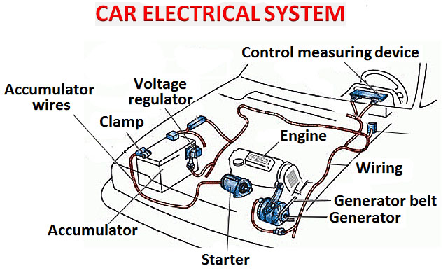
Automotive Electrical System Diagram
Understanding your automotive electrical system is key to diagnosing problems, performing modifications, and generally becoming a more confident car owner. While chasing wires can be frustrating, a good electrical system diagram is your roadmap. This article will break down the essentials of these diagrams, enabling you to read them effectively and use them for a variety of tasks.
Purpose: Your Road Map to Automotive Electrics
Why bother learning about electrical diagrams? Here's why they're invaluable:
- Troubleshooting Electrical Problems: Imagine a faulty tail light. A diagram lets you trace the circuit back to the source, identifying potential issues like a blown fuse, a broken wire, or a faulty switch. Without a diagram, you're essentially guessing.
- Performing Modifications: Planning to install aftermarket lights, a new stereo, or even an electric fan? A diagram shows you where to tap into the existing system, ensuring safe and proper connections. Crucially, it allows you to assess the circuit's load capacity and avoid overloading it.
- Understanding System Operation: Sometimes you just want to know how something works. An electrical diagram lays out the components and their relationships, helping you grasp the overall logic of the system.
- Repairing Damaged Wiring: Accidents happen. Whether it's rodent damage or frayed wires, a diagram helps you identify the correct wire gauge, color coding, and connections for proper repair.
Key Specs and Main Parts Depicted
Automotive electrical diagrams, also known as wiring schematics, depict the components of an electrical system and how they are connected. Here are the key components you'll typically find:
- Battery: The heart of the system, providing the necessary DC voltage (typically 12V in most vehicles). Represented by a symbol indicating positive and negative terminals.
- Fuses and Circuit Breakers: These protect the circuits from overcurrent situations. Fuses are represented by a symbol often resembling a squiggly line inside a rectangle; circuit breakers usually have a more complex symbol with a reset function indicated.
- Relays: Electrically operated switches that control high-current circuits with a low-current signal. Essential for controlling headlights, starters, and other power-hungry components. Represented by a coil (the electromagnet) and a switch symbol.
- Switches: Manually operated devices that open or close a circuit. Examples include light switches, ignition switches, and window switches. Represented by a break in the line to indicate an open switch or a continuous line for a closed switch.
- Wiring Harnesses: Bundles of wires that connect different components. Diagrams often show the main harnesses and their routing. Wire colors are *crucially* indicated.
- Grounds: Connection points where the electrical current returns to the negative terminal of the battery. Represented by a symbol that looks like a stack of horizontal lines.
- Sensors: Devices that measure various parameters, such as temperature, pressure, and speed. Their symbols vary depending on the sensor type.
- Actuators: Devices that perform a physical action based on an electrical signal. Examples include motors, solenoids, and injectors. Their symbols also vary.
- Control Modules (ECUs): Electronic control units (like the engine control unit, or ECU) that manage various systems in the vehicle. Represented by a rectangle with input and output connections.
Beyond the basic components, diagrams also specify important technical information, including:
- Wire Gauge: The thickness of the wire, indicated by a number (e.g., 16 AWG). A lower number indicates a thicker wire, capable of carrying more current.
- Wire Color: A critical detail for identifying the correct wire in a harness. Standard abbreviations are used (e.g., BLK for black, RED for red, GRN for green).
- Connector Locations: The physical location of connectors within the vehicle, often indicated by a code or diagram. This is incredibly helpful when tracing a circuit.
- Ground Locations: The exact points where circuits are grounded to the vehicle's chassis. These are vital for proper electrical operation.
Understanding Symbols: The Language of Diagrams
Electrical diagrams use a standardized set of symbols to represent different components. Learning these symbols is essential for reading and interpreting the diagrams. Here's a breakdown:
- Lines: Solid lines represent wires. Dashed lines may represent shielded cables or CAN bus lines (used for digital communication between ECUs).
- Colors: Wire colors are usually abbreviated (e.g., "RD" for red, "BLU" for blue). Sometimes, a color code will be indicated with a solid color, or as a stripe on another colored wire ("GRN/WHT" means green with a white stripe).
- Icons: Specific components have their own icons. Look for the battery symbol (short and long line), the resistor symbol (zigzag line), the capacitor symbol (parallel lines), and various symbols for relays, switches, and sensors. There are standardized symbols, but sometimes manufacturers use slightly different variations, so always check the diagram's key.
Pay attention to node points, which are indicated by dots where lines connect. A dot indicates a direct electrical connection. If lines cross without a dot, it usually means they are not connected.
How It Works: Following the Circuit
The beauty of an electrical diagram is that it allows you to trace the flow of current through a circuit. Start at the power source (the battery) and follow the wires through the various components (fuses, switches, relays, and ultimately the load, such as a light bulb or motor). Remember that current flows from the positive terminal to the negative terminal.
A basic circuit consists of:
- Power Source: The battery or alternator.
- Conductor: The wires that carry the current.
- Switch: To control the flow of current.
- Load: The device that uses the electricity (e.g., light bulb, motor).
- Ground: The return path for the current to the negative terminal of the battery.
By understanding this basic circuit, you can follow the current flow in more complex circuits depicted in the diagram.
Real-World Use: Basic Troubleshooting Tips
Here's how to use a diagram for basic troubleshooting:
- Identify the Problem: Determine the affected component or circuit.
- Locate the Diagram: Find the electrical diagram for the relevant system in your vehicle's repair manual or online database.
- Trace the Circuit: Follow the wires from the power source to the affected component. Look for breaks in the circuit, such as blown fuses, corroded connections, or damaged wires.
- Use a Multimeter: Use a multimeter to check for voltage, continuity, and resistance at various points in the circuit. This will help you pinpoint the location of the fault.
- Check Grounds: Ensure that all ground connections are clean and secure. A bad ground can cause a variety of electrical problems.
For example, if your headlights aren't working, the diagram will show you the fuse, the headlight switch, the relay (if equipped), and the wiring to the headlights. You can then use a multimeter to check for voltage at each of these points. A blown fuse will show zero voltage after the fuse; a faulty switch might not pass voltage when turned on; a bad ground will exhibit high resistance.
Safety First: Know the Risks
Working with automotive electrical systems can be dangerous. Here are some essential safety precautions:
- Disconnect the Battery: Always disconnect the negative terminal of the battery before working on the electrical system. This will prevent accidental shorts and electric shocks.
- Use Proper Tools: Use insulated tools designed for automotive electrical work.
- Work in a Well-Ventilated Area: Some electrical components can release harmful fumes.
- Be Careful with Airbags: Airbag systems are electrically activated. Improper handling can cause accidental deployment, which can be dangerous. Consult your vehicle's repair manual for specific instructions on disabling the airbag system before working near it.
- Capacitors can store a charge even after the battery is disconnected. Be careful when working around capacitors in the ECU or other modules. Discharge them safely before handling.
High-current circuits such as the starter and alternator circuits are particularly dangerous. Avoid working on these circuits unless you are confident in your abilities.
Having a good understanding of your vehicle's electrical system is empowering. With the right tools and a clear electrical diagram, you can tackle a wide range of repairs and modifications with confidence. Always remember to prioritize safety and consult a qualified mechanic if you are unsure about any aspect of the work.
For a more detailed electrical system diagram specific to your vehicle, refer to your vehicle's repair manual, or look for online resources specific to your make, model and year.
We have a sample diagram that you can download here.