
Automotive Electrical Wiring Connectors
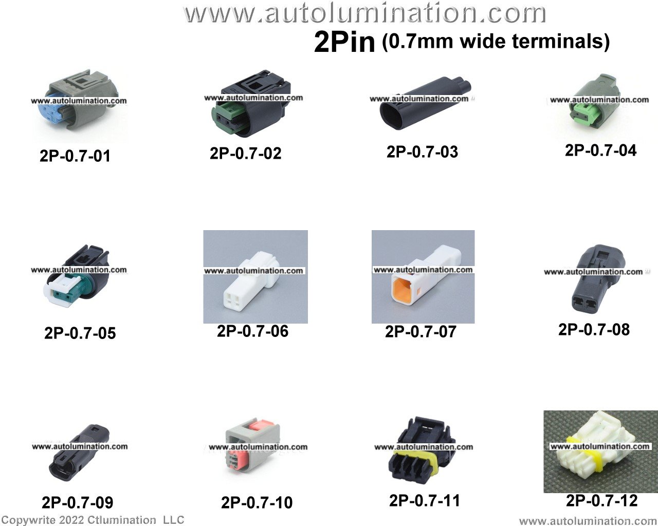
Automotive electrical wiring connectors are the unsung heroes of your car's complex network. They're the critical interfaces where wires meet, allowing signals and power to flow seamlessly throughout the vehicle. Understanding these connectors is essential for anyone tackling automotive electrical repairs, modifications, or even basic maintenance. This article dives deep into the world of automotive electrical connectors, providing you with the knowledge needed to confidently diagnose, repair, and even upgrade your vehicle's electrical system.
Purpose: Why Understanding Connectors Matters
Think of your car's wiring harness as its nervous system. Connectors are the synapses – the crucial points where information and power are transferred. Knowing how these connectors work and how to troubleshoot them is vital for several reasons:
- Repairs: A faulty connector is a common culprit behind electrical problems. Knowing how to identify, diagnose, and repair connector issues can save you time and money compared to blindly replacing expensive components.
- Modifications: Whether you're installing aftermarket lights, audio systems, or performance upgrades, you'll likely need to tap into the existing wiring. Understanding connectors allows you to do this safely and effectively.
- Diagnostics: Connectors are often the weak links in a circuit. When troubleshooting electrical issues, inspecting connectors for corrosion, damage, or loose connections should be one of your first steps.
- Learning: Gaining a deeper understanding of your car's electrical system empowers you to perform more advanced repairs and modifications.
Key Specs and Main Parts
Automotive electrical connectors come in a wide variety of shapes, sizes, and types, each designed for a specific application. Here's a breakdown of the key specs and main parts you'll encounter:
Key Specs:
- Pin Count: The number of individual wires the connector can accommodate (e.g., 2-pin, 4-pin, 12-pin).
- Wire Gauge (AWG): The size of the wire the connector is designed for. Using the wrong gauge connector can lead to poor connections or damage.
- Amperage Rating: The maximum amount of current the connector can safely handle. Exceeding this rating can cause overheating and failure.
- Environmental Protection: Some connectors are sealed to protect against moisture, dust, and other contaminants. Look for IP ratings (e.g., IP67) to indicate the level of protection.
- Locking Mechanism: The type of mechanism used to secure the connector halves together (e.g., friction lock, lever lock, threaded).
- Material: Connector housings are typically made from plastic (various types like nylon or polypropylene), while terminals are often made from brass or copper alloys, sometimes with plating (tin, silver, or gold) for corrosion resistance.
Main Parts:
- Housing: The outer shell of the connector, which provides protection and insulation for the terminals.
- Terminals: The metal contacts that make the electrical connection between the wires. These can be crimped, soldered, or insulation displacement connectors (IDCs).
- Seals: Rubber or silicone seals that prevent moisture and contaminants from entering the connector.
- Locking Mechanism: A feature (like a clip or lever) that secures the two halves of the connector together.
- Wire Seals (Grommets): Small rubber seals that fit around the wires as they enter the connector housing, providing additional environmental protection.
Symbols: Lines, Colors, and Icons
While not all connectors have standardized symbols on the connector itself, understanding general wiring diagram symbols is crucial when working with automotive electrical systems. Here's a basic overview:
- Lines: Represent wires. Thicker lines often indicate heavier gauge wires.
- Colors: Wires are typically color-coded to identify their function. Common colors include red (power), black (ground), and various other colors for signals. Refer to your vehicle's wiring diagram for the specific color code. Common abbreviations include: BK (Black), RD (Red), BL (Blue), GN (Green), YL (Yellow), WH (White), OR (Orange), BR (Brown), VT (Violet), GY (Gray).
- Icons: Represent components like switches, relays, fuses, and sensors. These icons are generally standardized across wiring diagrams.
Connector diagrams often show a simplified representation of the connector, indicating the pin numbers and wire colors associated with each pin. These diagrams are invaluable for identifying the correct wires and making proper connections.
How It Works
The basic principle of an electrical connector is simple: to create a reliable and secure electrical connection between two or more wires. The terminals inside the connector are designed to make a tight, low-resistance contact with the wires. This ensures that current can flow freely through the circuit without excessive voltage drop or heat buildup.
The housing protects the terminals from damage and environmental factors, while the locking mechanism prevents the connector from accidentally disconnecting. Seals are used to prevent moisture and contaminants from corroding the terminals and compromising the connection.
Modern connectors often use a "positive locking" mechanism, meaning an audible click is heard when the connector is fully engaged. This helps ensure a secure connection and reduces the risk of intermittent electrical problems.
Real-World Use: Basic Troubleshooting Tips
When troubleshooting electrical problems, always start by inspecting the connectors. Here are some basic troubleshooting tips:
- Visual Inspection: Look for signs of corrosion, damage, or loose connections. Check for broken or cracked housings, bent or broken terminals, and wires that are pulling out of the connector.
- Continuity Testing: Use a multimeter to check the continuity of the wires and terminals within the connector. This will help you identify broken wires or corroded terminals.
- Voltage Drop Testing: Use a multimeter to measure the voltage drop across the connector while the circuit is energized. Excessive voltage drop indicates a poor connection.
- Connector Cleaning: Use a specialized electrical contact cleaner to remove corrosion and dirt from the terminals.
- Terminal Repair: If a terminal is bent or damaged, you may be able to straighten it or replace it using specialized terminal repair tools.
- Proper Mating: Ensure the connector is fully seated and locked in place. A loose connection can cause intermittent electrical problems.
Important Note: Before working on any electrical circuit, disconnect the negative battery cable to prevent short circuits and electrical shock.
Safety: Highlight Risky Components
Working with automotive electrical systems can be dangerous if proper precautions are not taken. Here are some safety considerations:
- High-Voltage Circuits: Be extremely cautious when working with high-voltage circuits, such as those found in hybrid or electric vehicles. These circuits can deliver a lethal shock. Always follow the manufacturer's recommended procedures for disconnecting and discharging high-voltage systems.
- Airbag Systems: Airbag systems contain explosive charges. Disconnecting or tampering with airbag connectors can trigger accidental deployment, causing serious injury. Always follow the manufacturer's recommended procedures for disabling airbag systems before working on any electrical components near them.
- Fuel Injection Systems: Fuel injection systems operate at high pressure. Disconnecting fuel injectors without relieving the pressure can result in fuel spraying out, creating a fire hazard.
- General Precautions: Always wear safety glasses to protect your eyes from debris. Use insulated tools to prevent electrical shock. Disconnect the negative battery cable before working on any electrical circuit. Work in a well-lit and ventilated area.
Remember, when in doubt, consult a qualified automotive technician. Working with electrical systems can be complex and potentially dangerous, so it's always better to err on the side of caution.
By understanding the purpose, components, and troubleshooting techniques related to automotive electrical wiring connectors, you'll be well-equipped to tackle a wide range of electrical repairs and modifications. Always prioritize safety and consult the appropriate resources when working on your vehicle's electrical system. And if you are interested in a specific wiring diagram for your car, we have a vast collection available for download. Contact us to see if we have the one for your vehicle.