Automotive Electrical Wiring Diagram Symbols
Understanding automotive electrical wiring diagrams is crucial for anyone tackling DIY car repairs, modifications, or even just trying to better understand their vehicle's inner workings. Think of it as the blueprint of your car's electrical system. Without it, you're essentially working in the dark, risking damage to components and potentially even your own safety. This guide will break down the common symbols, layouts, and principles behind these diagrams, empowering you to diagnose problems and execute repairs with confidence.
Purpose and Importance
Why bother learning to read these diagrams? Here's a few compelling reasons:
- Troubleshooting: Quickly identify faulty circuits, locate shorts, and pinpoint open circuits. Instead of blindly testing wires, you can strategically focus your efforts.
- Repairs: Accurately trace wiring paths to replace damaged sections or repair connections. Avoiding unnecessary wire stripping and splicing saves time and reduces the risk of further problems.
- Modifications: Confidently add aftermarket accessories, such as lighting, audio systems, or performance upgrades, by safely integrating them into the existing electrical system. You can identify the correct power sources, ground points, and signal wires.
- Understanding: Gain a deeper understanding of how your vehicle's electrical system operates, enabling you to perform preventative maintenance and anticipate potential issues.
- Saving Money: By diagnosing and repairing electrical problems yourself, you can avoid costly trips to the mechanic.
Key Specs and Main Parts of a Wiring Diagram
A typical automotive wiring diagram will contain several key elements that work together to present a clear and comprehensive view of the electrical system. Understanding these parts is essential for effective diagram reading.
- Circuit Tracing: The primary function of the diagram is to show the path of electrical circuits from the power source (usually the battery) through various components and back to ground.
- Component Representation: Each electrical component (e.g., sensors, relays, switches, motors, lights) is represented by a specific symbol.
- Wire Identification: Wires are shown as lines, often with color codes and gauge information to help you identify them physically in the vehicle.
- Connectors and Ground Points: Connectors (where wires join together) and ground points (where circuits connect to the vehicle's chassis) are also indicated with specific symbols.
- Fuses and Relays: These crucial safety and control devices are clearly shown, along with their location in the system.
- Voltage and Current Flow: While not always explicitly stated, understanding the direction of current flow (from positive to negative) is fundamental to interpreting the diagram.
Deciphering the Symbols: Lines, Colors, and Icons
The language of wiring diagrams relies heavily on standardized symbols. Mastering these symbols is key to understanding the diagram's message.
Lines and Wires
- Solid Lines: Represent individual wires.
- Dashed Lines: Often indicate shielded cables or connections within a module.
- Wire Colors: Usually indicated by abbreviations (e.g., "RD" for Red, "BLU" for Blue, "BLK" for Black). Knowing these abbreviations is critical! The color code may be indicated along the line representing the wire.
- Wire Gauge: The thickness of the wire, usually expressed in American Wire Gauge (AWG). This is important for selecting the correct replacement wire during repairs.
Component Icons
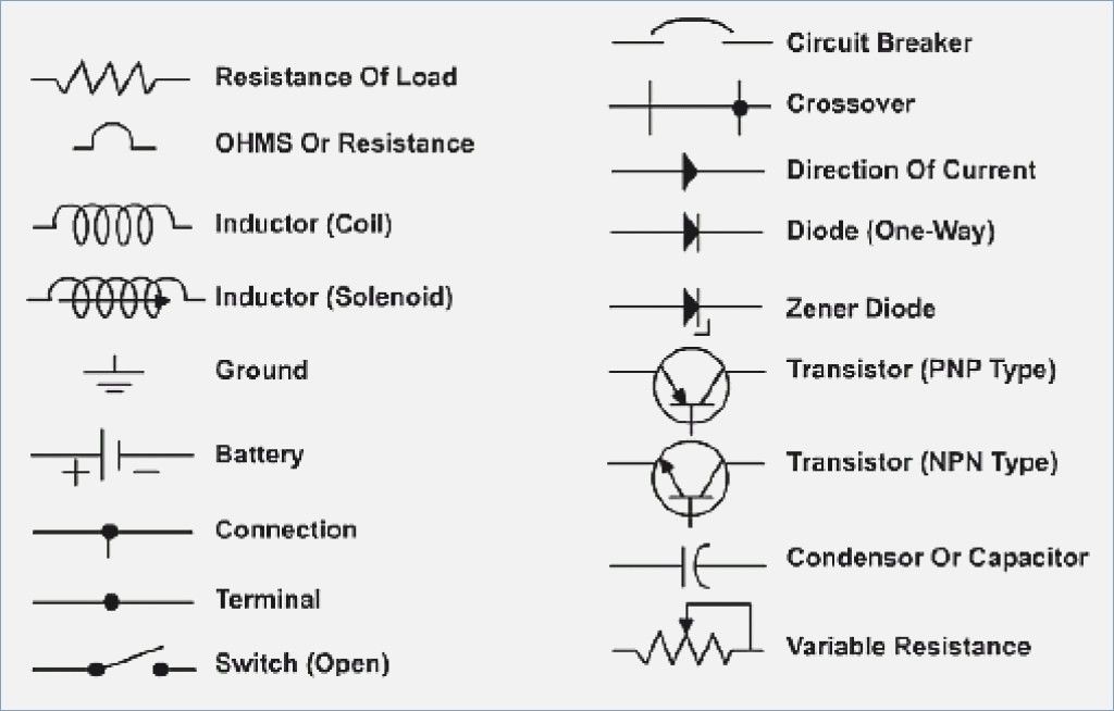
Component icons vary, but some are nearly universal:
- Resistor: A zig-zag line.
- Capacitor: Two parallel lines.
- Inductor: A series of loops.
- Ground: Often shown as three lines decreasing in length, pointing downwards and resembling an inverted Christmas tree.
- Battery: A series of short and long parallel lines, representing cells. The longer line indicates the positive terminal.
- Fuse: A squiggly line enclosed within a rectangle.
- Relay: A coil symbol representing the electromagnet, along with switch contacts that are opened or closed by the relay.
- Switch: A line representing a conductor that can be opened or closed to complete or break a circuit. Different switch types (e.g., SPST, SPDT, DPDT) have different symbols.
- Diode: A triangle pointing to a vertical line.
- Motor: A circle with an "M" inside.
- Lamp/Light Bulb: A circle with an "X" inside.
Important: Always refer to the specific wiring diagram's legend or key for a complete listing of symbols used, as conventions can vary slightly between manufacturers and even different models from the same manufacturer.
How It Works: Following the Circuit
Reading a wiring diagram involves tracing the flow of electricity through a circuit. Start at the power source (usually the battery), follow the wire through the various components, and ultimately back to ground. Each component plays a specific role in the circuit's operation. For example:
Example: A headlight circuit might start at the battery, go through a fuse (for protection), then to a headlight switch, then to the headlight bulb, and finally to a ground point on the vehicle's chassis.
Understanding the function of each component and how they are interconnected is crucial for diagnosing problems. If a headlight isn't working, you can use the diagram to systematically check the fuse, switch, bulb, and wiring connections.
Real-World Use: Basic Troubleshooting Tips
Here's how you can put your newfound knowledge to practical use:
- Identify the Circuit: Use the vehicle's service manual or online resources to find the wiring diagram for the specific system you're working on.
- Trace the Path: Follow the circuit from the power source to the component in question.
- Check for Voltage: Use a multimeter to check for voltage at key points along the circuit. A lack of voltage indicates a break in the circuit, such as a blown fuse, a broken wire, or a faulty switch.
- Check for Continuity: Use a multimeter to check for continuity (a complete electrical path) in the wiring and components. A lack of continuity indicates an open circuit, such as a broken wire or a faulty component.
- Inspect Connections: Visually inspect connectors for corrosion, loose connections, or damaged wiring. Clean and tighten connections as needed.
Pro Tip: When troubleshooting, always start with the simplest and most likely causes first. For example, check the fuse before tearing apart the wiring harness.
Safety First: Handling Risky Components
Working with automotive electrical systems can be dangerous. Always take the following precautions:
- Disconnect the Battery: Before working on any electrical system, disconnect the negative battery cable to prevent shorts and electrical shocks.
- Work in a Well-Ventilated Area: Battery acid and other chemicals can release harmful fumes.
- Use Proper Tools: Use insulated tools designed for automotive electrical work.
- Never Bypass Fuses: Fuses are designed to protect the circuit from overloads. Bypassing a fuse can lead to serious damage and even fire.
- Be Aware of High-Voltage Components: Some components, such as the ignition system and the hybrid system, can carry high voltages that can be lethal. Take extra caution when working around these components. Never probe these components without proper training and equipment.
Warning: Working with the airbag system is particularly dangerous. Improper handling can cause the airbags to deploy, resulting in serious injury. If you are not experienced with airbag systems, leave the repairs to a qualified technician.
Now that you have a good understanding of wiring diagram symbols and troubleshooting, remember to take your time, be methodical, and always prioritize safety. With practice, you'll be able to confidently tackle many automotive electrical repairs yourself.
For your convenience, we have a comprehensive wiring diagram file available for download. This resource will provide you with detailed schematics and symbol definitions to aid in your troubleshooting and repair endeavors.