
Automotive Electrical Wiring Diagrams
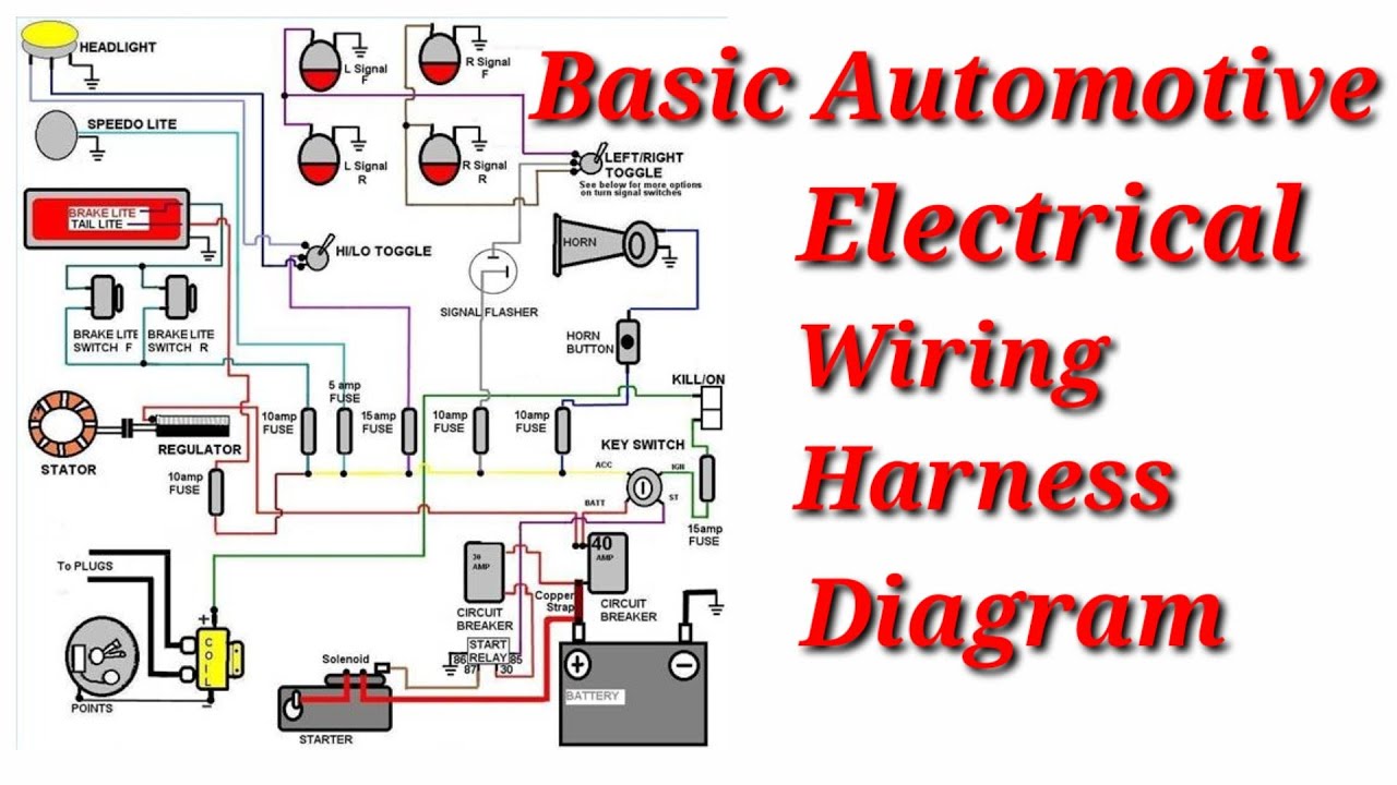
So, you're ready to dive into the fascinating world of automotive electrical wiring diagrams, huh? Good! Because understanding these schematics is absolutely crucial for anyone serious about maintaining, modifying, or repairing their vehicle's electrical system. Forget relying solely on guesswork; a wiring diagram is your roadmap to electrical enlightenment. We have a library of diagrams available, and you can download the specific one for your vehicle's year and model. This article will help you navigate it effectively.
Purpose of Automotive Electrical Wiring Diagrams
Why bother with these seemingly complex drawings? Simple: they provide a clear, organized representation of your car's entire electrical system. Here's why they're invaluable:
- Troubleshooting: When your headlights flicker, your stereo dies, or your engine refuses to start, a wiring diagram can pinpoint the exact faulty circuit or component. Trace the wiring, check voltage, and isolate the issue quickly.
- Repairing: Once you've found the problem, the diagram shows you how to fix it. Which wires to splice, which connectors to clean, which components to replace.
- Modifying: Want to install that new sound system, add auxiliary lighting, or upgrade your alarm system? A wiring diagram ensures you tap into the correct circuits without causing shorts or damaging sensitive electronics.
- Understanding: Even if you're not actively repairing anything, studying the diagram gives you a deeper understanding of how your car's electrical system works. You'll learn how various components are connected, how they interact, and how they're protected by fuses and relays.
Key Specs and Main Parts
Before we decipher the symbols, let's understand the key elements depicted in a typical automotive electrical wiring diagram:
- Power Source: Usually the car's battery (represented by a symbol resembling parallel lines of differing lengths). From the battery, power is distributed throughout the system.
- Ground: The return path for the electrical current. Ground connections are usually bolted to the vehicle's chassis, providing a common reference point (represented by a downward-pointing triangle or a series of decreasing parallel lines). A good ground is *essential* for proper circuit function.
- Wiring: Represents the actual wires connecting different components. These are shown as lines, often color-coded to indicate their function (more on this later).
- Components: These are the individual parts of the electrical system, such as lights, motors, sensors, switches, relays, and control modules (ECUs). Each component has a specific symbol.
- Connectors: These are the points where wires are joined together, often using multi-pin connectors. They're represented by various symbols, sometimes showing the number of pins.
- Fuses and Circuit Breakers: Protective devices that interrupt the circuit when excessive current flows, preventing damage to the wiring and components. Represented by a zigzag line or a rectangular box with a specific symbol.
- Relays: Electrically operated switches that allow a low-current circuit to control a high-current circuit (e.g., using a small switch to control the high-power starter motor). Represented by a coil symbol and a switch symbol.
- Splices: Points where wires are joined together permanently. They are usually represented by a dot where lines intersect.
Symbols – Lines, Colors, and Icons
Decoding the symbols is crucial for understanding the diagram. Here's a breakdown:
Lines
- Solid lines: Represent wires. Thicker lines may indicate larger gauge wires carrying more current.
- Dashed lines: May represent shielded wires, communication buses (like CAN bus), or ground connections. The diagram's legend should clarify what dashed lines mean in that specific context.
- Arrows: Indicate the direction of current flow (conventional current flow – positive to negative, though electron flow is actually the opposite).
Colors
Wire colors are standardized to some extent, but can vary between manufacturers and even models. The diagram's legend *always* provides the color code. Common colors include:
- Red: Often used for battery power or ignition power.
- Black: Usually indicates ground.
- Yellow: Can be used for various circuits, often lighting.
- Blue: Can be used for various circuits.
- Green: Often used for signal wires, like sensor outputs.
- Combinations: Wires may have a base color with a stripe (e.g., "Red/White" indicates a red wire with a white stripe).
Icons
Each component has a specific icon. Here are some examples:
- Battery: Two parallel lines of different lengths.
- Light Bulb: A circle with an "X" inside.
- Resistor: A zigzag line.
- Capacitor: Two parallel lines of equal length.
- Diode: A triangle pointing to a line.
- Motor: A circle with an "M" inside.
- Switch: A line bridging two points (open or closed depending on the switch state).
- Ground: A downward-pointing triangle or a series of decreasing parallel lines.
Again, *always* refer to the diagram's legend for the complete list of symbols used.
How It Works
Think of the wiring diagram as a map. Start at the power source (battery) and trace the circuit you're interested in. Follow the lines (wires) through the various components (switches, relays, fuses, lights, etc.) until you reach the ground. The diagram shows you how the circuit is completed, and how each component interacts with the others.
For example, if you're troubleshooting a headlight issue, you would:
- Locate the headlight circuit in the diagram.
- Trace the power from the battery, through the fuse, through the switch, to the headlight, and then to ground.
- Use a multimeter to check for voltage at each point in the circuit. If you find a point where the voltage is missing, you've located the fault (e.g., a blown fuse, a faulty switch, a broken wire).
Real-World Use – Basic Troubleshooting Tips
Here are a few basic troubleshooting tips using a wiring diagram:
- No Power: If a component isn't working, check for power at the component using a multimeter. If no power, trace the circuit back towards the battery, checking fuses, relays, and switches along the way.
- Ground Issues: Ensure a good ground connection. Clean any corroded ground points.
- Continuity Testing: Use a multimeter to check for continuity in wires. If there's no continuity, the wire is broken.
- Voltage Drop: A significant voltage drop across a component indicates a problem (e.g., a corroded connection or a failing component).
Safety
Working with automotive electrical systems can be dangerous. Here are some safety precautions:
- Disconnect the Battery: Always disconnect the negative battery cable before working on the electrical system to prevent shorts and accidental activation of components.
- High-Voltage Components: Be extremely careful around high-voltage components like the ignition system and hybrid vehicle systems. These can deliver a lethal shock. *Never* probe or touch these components unless you are properly trained and equipped.
- Airbags: Airbag systems are also dangerous. *Never* probe or disconnect airbag components without following the manufacturer's specific procedures for disabling the system. Accidental airbag deployment can cause serious injury.
- Use Proper Tools: Use insulated tools to prevent shorts and electrical shocks.
- Work in a Well-Ventilated Area: Some automotive chemicals and fumes can be harmful.
Remember to consult the specific wiring diagram for *your* vehicle's make, model, and year. There will be differences between vehicles. Automotive wiring diagrams are a crucial tool for any DIY mechanic, and can save a lot of time and money by helping you troubleshoot your car's electrical system with confidence.