Automotive Electrical Wiring Harness
So, you're thinking about diving into automotive electrical wiring, huh? Smart move. Understanding your car's wiring harness is like learning the language of its nervous system. It allows you to perform repairs, install aftermarket accessories with confidence, diagnose problems accurately, and even customize your ride to your exact specifications. We're talking about serious DIY power here. This article is your guide to understanding the complexities of automotive electrical wiring harnesses, giving you the knowledge to tackle more advanced projects.
Purpose of Understanding Wiring Harnesses
Let's be clear: automotive electrical systems can seem daunting. But a solid grasp of the wiring harness is essential for anyone serious about car maintenance and modification. Knowing how to read and interpret a wiring diagram unlocks a world of possibilities. Think about it:
- Repairs: Diagnosing and fixing electrical faults becomes significantly easier. You can trace wires, identify shorts or opens, and replace damaged sections with precision.
- Modifications: Adding aftermarket lights, stereos, alarms, or other electronic accessories requires understanding how to integrate them safely and correctly into the existing wiring.
- Troubleshooting: Electrical gremlins are notoriously difficult to track down. Knowing how the wiring harness is laid out helps you systematically eliminate potential causes.
- Learning: Understanding wiring harnesses builds a deep understanding of how your car functions, leading to further learning in other automotive areas.
Having the proper wiring diagram for your specific vehicle is absolutely crucial. It's the roadmap you need. Luckily, we have a downloadable version available (link at the end of the article) to help you follow along and reference while you work.
Key Specs and Main Parts of a Wiring Harness
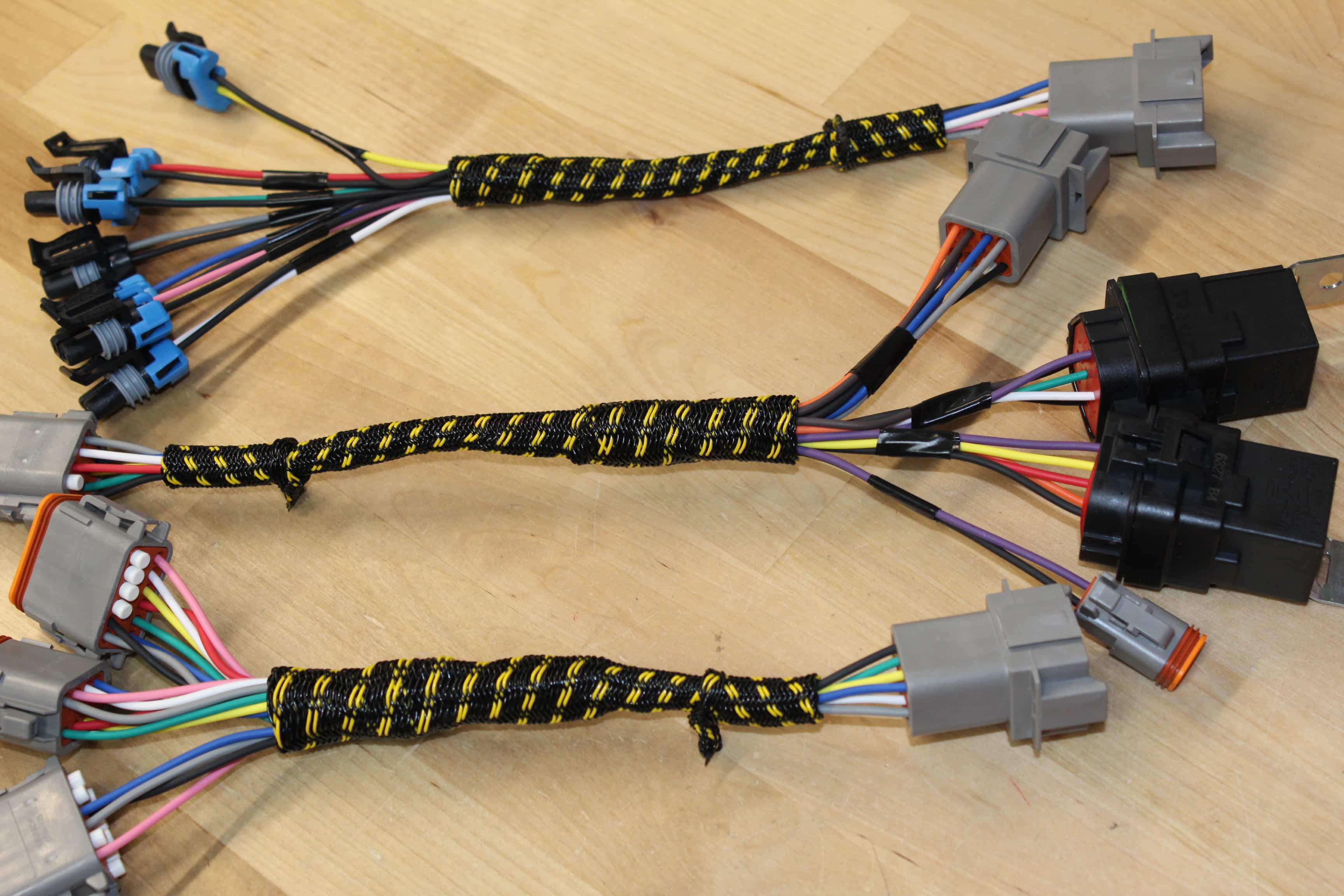
A wiring harness, at its core, is an organized assembly of wires, connectors, and terminals designed to transmit electrical power and signals throughout a vehicle. Here's a breakdown of the key components:
- Wires: These are the arteries of the electrical system, carrying current from the power source (battery, alternator) to various components. Automotive wires are typically stranded copper, offering flexibility and resistance to vibration. Wire gauge, measured in AWG (American Wire Gauge), indicates the wire's diameter and current-carrying capacity. Smaller AWG numbers represent thicker wires capable of handling higher currents. You'll often see 18 AWG, 16 AWG, and 14 AWG used for various circuits.
- Connectors: These provide secure and reliable connections between wires and components. They come in various shapes, sizes, and pin configurations, designed for specific applications. Connectors often incorporate locking mechanisms to prevent accidental disconnection.
- Terminals: These are the metal contacts that fit inside connectors, crimped or soldered onto the wire ends. Proper crimping is essential for a reliable electrical connection. Poorly crimped terminals are a major cause of electrical problems.
- Grounding Points: These are critical locations where electrical circuits are connected to the vehicle's chassis, providing a return path for the current. Good grounding is essential for proper circuit operation.
- Fuses and Relays: Fuses are safety devices that protect circuits from overcurrent. They contain a thin wire that melts and breaks the circuit if the current exceeds a certain limit. Relays are electromechanical switches that allow a low-current circuit to control a high-current circuit. They're commonly used to switch on headlights, fuel pumps, and other high-power devices.
- Splices: These are points where multiple wires are joined together. In modern harnesses, splices are often sealed and protected within a molded housing.
- Protective Covering: The entire harness is typically wrapped in protective materials like electrical tape, convoluted tubing (split loom), or heat shrink tubing to protect the wires from abrasion, heat, and moisture.
Understanding Wiring Diagram Symbols
Wiring diagrams use a standardized set of symbols to represent different components and connections. Learning to decipher these symbols is crucial for interpreting the diagram accurately. Here are some common symbols you'll encounter:
- Lines: These represent wires. A solid line indicates a direct connection, while a dashed line may indicate a shielded wire or a connection through a connector. The color of the line typically indicates the wire color, which is essential for tracing circuits.
- Circles: Often represent lamps or indicators.
- Squares and Rectangles: Commonly used to represent switches, relays, and control modules. The internal configuration of the symbol indicates the function of the component.
- Resistors: Zigzag lines represent resistors.
- Capacitors: Two parallel lines represent capacitors.
- Ground Symbol: Typically a series of downward-pointing lines, indicating a connection to the vehicle's chassis ground.
- Connectors: Represented by various shapes, often resembling interlocking tabs. The diagram will usually include a connector number or location for easy identification.
- Wire Colors: Standard abbreviations are used for wire colors: BK (Black), RD (Red), BL (Blue), GN (Green), YL (Yellow), WH (White), OR (Orange), BR (Brown), VT (Violet). Often, you'll see combinations, like "RD/BK" for a red wire with a black stripe.
Remember that wiring diagrams may have slight variations in symbols depending on the manufacturer and the age of the vehicle. However, the basic principles remain the same. Consult your specific vehicle's service manual for the most accurate and detailed wiring diagrams.
How It Works: Tracing a Circuit
The real power of a wiring diagram lies in its ability to show you how a circuit functions. Let's walk through a simplified example of how to trace a circuit:
- Identify the Component: Start with the component you're interested in, such as a headlight. Find its symbol on the wiring diagram.
- Follow the Power: Trace the wire connected to the headlight back towards the power source. This will typically lead you to a fuse, a relay, or a switch.
- Note Wire Colors: Pay attention to the wire colors along the way. This helps you physically locate the wire in the harness.
- Identify Connectors: Note the connector locations where the wire passes through. This helps you break down the circuit into manageable sections.
- Follow the Ground: Trace the ground wire from the headlight back to a grounding point on the chassis.
- Understand the Switching: If the headlight is controlled by a switch, understand how the switch connects and disconnects the power to the headlight. This involves tracing the wires from the switch to the power source and the headlight.
By following these steps, you can understand the entire path of the electrical current in the circuit, from the power source to the component and back to ground. This knowledge is invaluable for troubleshooting electrical problems.
Real-World Use: Basic Troubleshooting Tips
Here are some basic troubleshooting tips using your understanding of the wiring harness:
- No Power to a Component: Check the fuse for the circuit. If the fuse is blown, replace it with the correct amperage rating. If the fuse blows repeatedly, there's likely a short circuit somewhere in the wiring. Use the wiring diagram to trace the circuit and locate the short.
- Intermittent Problems: Loose connections are a common cause of intermittent electrical problems. Check the connectors in the circuit for corrosion or damage. Clean the contacts with electrical contact cleaner and ensure they are securely connected.
- Grounding Issues: Poor grounding can cause all sorts of strange electrical problems. Ensure that all grounding points are clean and securely connected to the chassis.
- Using a Multimeter: A multimeter is an essential tool for electrical troubleshooting. You can use it to measure voltage, current, and resistance. Use the wiring diagram to identify the correct points to measure these parameters.
Safety First: Highlighting Risky Components
Automotive electrical systems can be dangerous if not handled properly. Here are some safety precautions to keep in mind:
- Disconnect the Battery: Always disconnect the negative battery terminal before working on any electrical system. This prevents accidental shorts and electrical shocks.
- Work in a Well-Ventilated Area: When soldering or using chemical cleaners, work in a well-ventilated area to avoid inhaling harmful fumes.
- Use Insulated Tools: Use tools with insulated handles to protect yourself from electrical shock.
- Never Work on the Airbag System: Airbag systems contain explosives and should only be serviced by qualified technicians. Accidental deployment can cause serious injury.
- Be Careful Around High-Voltage Components: Some vehicles have high-voltage components, such as hybrid or electric vehicle batteries. These components can be extremely dangerous and should only be serviced by trained professionals.
The high current carrying components, such as starter and alternator cables, pose a significant risk if shorted to ground. Exercise extreme caution when working near these components.
Understanding your car's wiring harness is a powerful tool that can save you time, money, and frustration. By learning the basics of wiring diagrams and electrical troubleshooting, you can confidently tackle more advanced automotive projects. Remember to always prioritize safety and consult your vehicle's service manual for specific information. And of course, remember we have a downloadable wiring diagram file available for you to use as a reference.
As promised, you can download a sample wiring diagram file here.