
Automotive Electrical Wiring Supplies
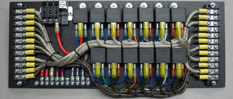
Understanding your automotive electrical wiring is crucial whether you're performing simple repairs, installing aftermarket accessories, or simply expanding your knowledge of how your vehicle functions. This guide provides a detailed look at automotive electrical wiring supplies, covering everything from their purpose to troubleshooting common issues.
Purpose of Understanding Automotive Electrical Wiring
Automotive electrical systems, while seemingly complex, are built upon fundamental principles. Having a solid grasp of wiring allows you to:
- Perform Repairs: Diagnose and fix broken wires, faulty connectors, and component failures without relying solely on expensive professional services.
- Install Accessories: Safely and correctly install aftermarket devices like stereos, lights, alarms, and performance enhancements. This ensures proper function and prevents electrical fires.
- Understand Vehicle Function: Gain a deeper understanding of how different systems interact within your vehicle, leading to better troubleshooting and preventative maintenance.
- Modify and Customize: Safely modify your vehicle's electrical system to meet specific needs or desires, such as adding custom lighting or integrating new control systems.
- Preventative Maintenance: Spot potential wiring issues early and prevent failures.
Key Specifications and Main Parts
Automotive wiring involves various components, each with specific specifications and purposes. Let's break down the key elements:
Wires
Gauge: The wire gauge (AWG - American Wire Gauge) indicates the wire's diameter and, consequently, its current-carrying capacity. Lower gauge numbers indicate thicker wires that can handle more amperage. Common gauges include 18 AWG (low current), 16 AWG (moderate current), 14 AWG (medium current), 12 AWG (high current), and 10 AWG (very high current).
Insulation: Automotive wire insulation is typically made of high-temperature PVC (Polyvinyl Chloride) or cross-linked polyethylene (XLPE) to withstand engine compartment heat. The insulation also protects the wire from abrasion and chemical exposure.
Stranding: The number of individual strands making up the wire conductor. More strands result in a more flexible wire, which is crucial for automotive applications where wires are constantly subjected to vibration and movement.
Connectors
Connectors provide secure and reliable connections between wires and components. Types include:
- Butt Connectors: Used for joining two wires end-to-end. They are crimped onto the exposed conductors.
- Spade Connectors: Male or female connectors used to attach wires to terminals on components.
- Ring Terminals: Connect wires to ground points or bolts using a circular terminal.
- Bullet Connectors: Similar to spade connectors but with a cylindrical shape.
- Weatherpack/Deutsch Connectors: Sealed connectors designed to protect connections from moisture and contaminants. Essential for under-hood and exterior applications.
Fuses and Circuit Breakers
These are essential safety devices that protect the electrical system from overloads. Fuses are designed to melt and break the circuit when the current exceeds a specified level. Circuit breakers automatically interrupt the circuit and can be reset.
Amperage Rating: The amperage rating indicates the maximum current the fuse or circuit breaker can handle before tripping or blowing.
Relays
Relays are electrically operated switches used to control high-current circuits with a low-current signal. They're often used to control headlights, horns, and other high-power accessories.
Coil Voltage: The voltage required to activate the relay's coil.
Contact Rating: The maximum current and voltage the relay's contacts can handle.
Grounding Straps and Wires
Provide a path for current to return to the battery, completing the circuit. Good grounding is crucial for proper electrical system operation.
Symbols in Automotive Wiring Diagrams
Wiring diagrams use standardized symbols to represent components and connections. Understanding these symbols is key to interpreting the diagram.
- Solid Lines: Represent wires.
- Dashed Lines: Often indicate shielded wires or wires that are part of a harness.
- Circles: Can represent lamps, sensors, or other components.
- Squares/Rectangles: Typically represent control modules or relays.
- Ground Symbol: A downward-pointing arrow or a series of horizontal lines indicates a ground connection.
- Fuse Symbol: A zigzag line within a rectangle.
- Switch Symbol: A line that can be connected or disconnected to represent the switch's state.
Wire Colors: Wire colors are often indicated with abbreviations (e.g., BK for Black, RD for Red, BL for Blue, GR for Green, YL for Yellow, WT for White). Knowing the color code helps you identify specific wires within a harness.
How Automotive Electrical Wiring Works
Automotive electrical systems operate on the principle of a closed circuit. Current flows from the battery, through a component (e.g., a light bulb), and back to the battery via a ground connection. The battery provides the voltage (electrical potential) that drives the current.
Series Circuits: Components are connected one after another, so the same current flows through each component. If one component fails, the entire circuit breaks.
Parallel Circuits: Components are connected side-by-side, so each component receives the full battery voltage. If one component fails, the other components continue to function.
Most automotive circuits are a combination of series and parallel connections.
Real-World Use: Basic Troubleshooting Tips
When troubleshooting electrical problems, start with the basics:
- Check Fuses: This is the first step. Use a test light or multimeter to check for continuity across the fuse. A blown fuse indicates an overload.
- Inspect Connectors: Look for corroded, loose, or broken connectors. Clean and re-seat connectors as needed. Use dielectric grease to prevent future corrosion.
- Check Ground Connections: Ensure all ground connections are clean, tight, and free of corrosion. A poor ground can cause a variety of electrical problems.
- Use a Multimeter: A multimeter is an essential tool for measuring voltage, current, and resistance. Use it to check for voltage at various points in the circuit, to measure current flow, and to test for continuity.
- Check Wiring for Damage: Look for frayed wires, cracked insulation, or rodent damage. Repair or replace damaged wires.
Example: If your headlights don't work, start by checking the headlight fuse. If the fuse is good, check the headlight relay. If the relay is good, use a multimeter to check for voltage at the headlight connector. If there's no voltage, trace the wiring back to the relay and look for breaks or shorts.
Safety Considerations
Working with automotive electrical systems can be dangerous. Take the following precautions:
- Disconnect the Battery: Always disconnect the negative battery terminal before working on any electrical circuits. This prevents accidental shorts and potential electrical shocks.
- Avoid Working in Wet Conditions: Water conducts electricity, increasing the risk of electrical shock.
- Use Insulated Tools: Use tools with insulated handles to protect yourself from electrical shock.
- Be Careful Around the Airbag System: Airbag systems are sensitive and can deploy unexpectedly if mishandled. Refer to your vehicle's service manual for specific instructions on disabling the airbag system before working near it.
- Be mindful of the ECM (Engine Control Module), TCU (Transmission Control Unit), ABS (Anti-lock Braking System) and other critical systems: Tampering with these systems may have disastrous effects, use caution and research the possible outcomes and solutions.
- Work in a well-ventilated area: When soldering or using chemicals, work in a well-ventilated area to avoid inhaling harmful fumes.
High-Risk Components: Capacitors in the ECM or other control modules can store a significant electrical charge even after the battery is disconnected. Discharge capacitors properly before handling these components. Follow manufacturers recommendations. Similarly, working with the SRS (Supplemental Restraint System) or airbag system requires extreme care and specific procedures. Airbags can deploy unexpectedly if mishandled.
We have a detailed automotive electrical wiring diagram available for download. This diagram can be an invaluable resource for understanding the specific wiring of your vehicle and for troubleshooting electrical problems. It contains detailed schematics and wiring information to help you with your automotive electrical tasks.