
Automotive Wiring Diagram Color Codes
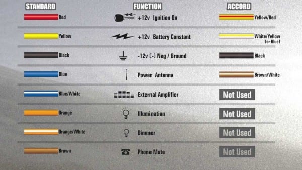
Understanding automotive wiring diagrams is crucial for anyone tackling car repairs, modifications, or even just wanting a deeper understanding of their vehicle's electrical system. These diagrams are essentially roadmaps to your car's electrical circuits, and deciphering them can save you time, money, and prevent potential damage. This article will demystify automotive wiring diagram color codes, equipping you with the knowledge to confidently navigate these essential documents.
Purpose of Automotive Wiring Diagrams
Why bother learning to read wiring diagrams? Several compelling reasons exist:
- Troubleshooting: Locating shorts, opens, and other electrical faults becomes significantly easier when you can trace the circuit path. Forget guessing – pinpoint the problem area directly.
- Repairs: Replacing a faulty component or repairing damaged wiring is much safer and more efficient with a diagram to guide you.
- Modifications: Adding aftermarket accessories like lights, stereos, or alarms requires tapping into existing circuits. A diagram ensures you're connecting to the correct wires and protecting your system.
- Learning: Understanding wiring diagrams provides a deeper appreciation for how your car's electrical system functions, leading to a better understanding of automotive technology overall.
Key Specs and Main Parts of a Wiring Diagram
A typical automotive wiring diagram isn't just a chaotic mess of lines. It's an organized representation with several key elements:
- Circuit Identification: Each circuit (e.g., headlights, fuel pump) is usually labeled with a descriptive name or code.
- Component Symbols: Symbols represent various electrical components like switches, relays, fuses, resistors, motors, and sensors.
- Wire Colors: Wires are depicted with different colors or color codes, acting like a map to help you physically locate them in the vehicle. This is our main focus today.
- Ground Points: Identified by a specific symbol, ground points indicate where the circuit returns to the vehicle's chassis.
- Connectors: Symbols show where wires connect to each other through connectors. These are often numbered for easy identification.
- Splices: A splice indicates where one wire branches into multiple wires.
- Voltage Values: Some diagrams may indicate voltage values at specific points in the circuit, aiding in troubleshooting.
- Fuse and Relay Locations: The diagram often includes information about the physical location of fuses and relays within the vehicle.
Symbols: Lines, Colors, and Icons
Understanding the symbolism is critical for diagram interpretation:
Lines
- Solid Lines: Represent continuous wires.
- Dashed Lines: May indicate a shielded wire or a wire that is part of a harness.
- Lines with Arrows: Show the direction of current flow.
- Thick Lines: Sometimes indicate a wire with a larger gauge (thicker conductor), capable of carrying more current.
Colors
Color codes are the most important aspect of tracing wires. A standardized system is generally used, but slight variations can occur between manufacturers. Here's a common breakdown:
- BK: Black (often ground)
- BN: Brown
- BU: Blue
- DG: Dark Green
- GN: Green
- GY: Gray
- LB: Light Blue
- LG: Light Green
- OR: Orange
- PK: Pink
- RD: Red
- VT: Violet
- WH: White
- YE: Yellow
Often, you'll see combinations like "RD/BK" which indicates a red wire with a black stripe. The first color is the primary color, and the second is the stripe color. Sometimes, you may see three letter codes, where the third letter often represents the *shade* or *tone* of the color itself.
Icons
Icons represent various components. Here are a few common examples:
- Resistor: A zig-zag line.
- Capacitor: Two parallel lines.
- Coil/Inductor: A coiled line.
- Diode: A triangle pointing to a vertical line.
- Fuse: A squiggly line inside a rectangle or circle.
- Relay: A coil symbol connected to a switch symbol.
- Switch: A break in a line that can be closed or opened. Different switch configurations (SPST, SPDT, DPST, DPDT) have different symbols.
- Ground: Typically represented by a series of lines getting smaller and going to ground. Can also be a filled triangle.
How It Works: Tracing a Circuit
Let's say you want to trace the circuit for your headlights. Start by locating the headlight circuit in the diagram. You'll see a power source (usually the battery), a fuse, a switch (the headlight switch), relays (if applicable), and the headlights themselves. Begin at the power source and follow the lines, noting the wire colors at each point. If you encounter a connector, the diagram should indicate the connector number and pin number, allowing you to locate the corresponding connector in your car. By carefully tracing the circuit, you can identify potential fault locations, such as a broken wire, a faulty switch, or a blown fuse. *The color codes are critical* as they help you physically identify the wires in your car that correspond to the diagram.
Remember that each component in the circuit must function correctly for the circuit to operate. A break at any point along the chain will prevent the flow of electricity.
Real-World Use: Basic Troubleshooting Tips
Here are some basic troubleshooting tips using wiring diagrams:
- No Power: If a circuit isn't working, check the fuse first. The diagram will show its location and amperage. If the fuse is blown, replace it. If it blows again immediately, there's a short circuit downstream.
- Voltage Drop: Use a multimeter to measure the voltage at different points in the circuit. A significant voltage drop indicates resistance, potentially due to a corroded connection or a damaged wire.
- Continuity Testing: Disconnect the circuit from the power source and use a multimeter in continuity mode to check for broken wires. The meter should show continuity (close to zero resistance) if the wire is intact.
- Backprobing: Instead of piercing the insulation on a wire to test it, which can lead to corrosion, use a backprobing kit. This allows you to test the wire through the back of a connector without damaging it.
Always disconnect the battery's negative terminal before working on any electrical circuit. This prevents accidental shorts and potential damage to your car's electronics.
Safety: Highlight Risky Components
Certain components can be particularly risky to work with:
- Airbag System: The airbag system contains explosive devices. *Never tamper with airbag wiring unless you are properly trained and have the correct tools.* Accidental deployment can cause serious injury.
- High-Voltage Systems (Hybrid/Electric Vehicles): These vehicles have high-voltage systems that can be lethal. *Only qualified technicians should work on these systems.*
- Fuel Pump: Working on the fuel pump circuit requires caution to prevent fuel spills and potential fire hazards. Always disconnect the battery and work in a well-ventilated area.
Understanding the wiring diagram helps you avoid these potentially dangerous components.
By carefully studying wiring diagrams and applying basic troubleshooting techniques, you can confidently diagnose and repair electrical problems in your car. Remember to always prioritize safety and double-check your work. The ability to interpret these diagrams is a valuable skill that empowers you to take control of your car's maintenance and modifications.
To further assist you, we have a sample automotive wiring diagram file available for download. This file provides a practical example of the concepts discussed in this article and can serve as a valuable reference tool for your future projects.