
Automotive Wiring Harness Repair Near Me
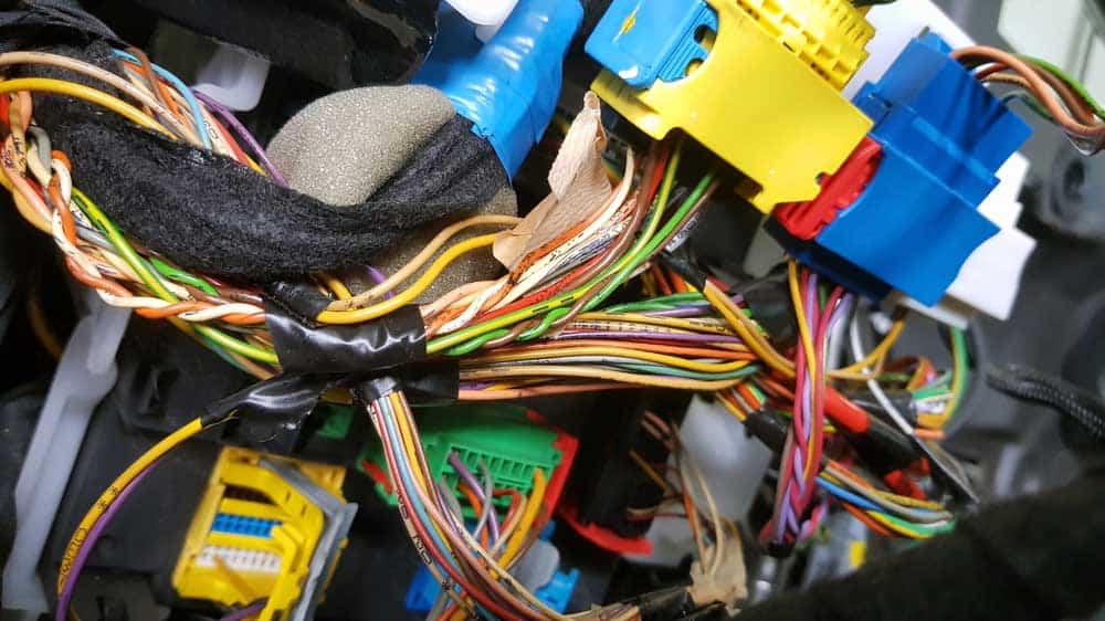
You're knee-deep in an automotive wiring project, troubleshooting an electrical gremlin, or maybe just upgrading your sound system. Understanding your car's wiring harness is absolutely critical. Finding a qualified mechanic specializing in "automotive wiring harness repair near me" is a great option, but sometimes tackling the problem yourself, armed with the right knowledge, is the most satisfying (and cost-effective) route. This guide aims to equip you with the knowledge you need to decipher wiring diagrams and perform basic repairs, making you more confident and efficient in your electrical endeavors.
Why Wiring Diagrams Matter
Wiring diagrams are essentially the blueprints of your car's electrical system. They depict how all the electrical components are connected, showing wire routing, connector locations, and the flow of electricity. Understanding these diagrams is vital for:
- Troubleshooting Electrical Problems: Pinpointing the source of a short circuit, open circuit, or voltage drop.
- Performing Repairs: Replacing damaged wires, connectors, or components correctly.
- Adding Aftermarket Accessories: Safely and effectively integrating new components like lights, alarms, or audio systems.
- Understanding Vehicle Systems: Gaining a deeper understanding of how different systems interact and function.
- Preventing Further Damage: Incorrect wiring can cause fires, damage electronic control units (ECUs), and render your vehicle inoperable.
Essentially, a good understanding of wiring diagrams transforms you from a guesser to a diagnostician, significantly reducing wasted time and potential damage.
Key Specs and Main Parts of a Wiring Diagram
Let's break down the anatomy of a typical automotive wiring diagram. These diagrams might seem intimidating at first, but they follow standardized conventions.
Key Specifications
- Vehicle Make, Model, and Year: Crucial for ensuring the diagram matches your specific vehicle. Variations even within the same model year can exist.
- System Covered: The diagram should specify which system it covers (e.g., engine management, lighting, ABS).
- Revision Level: Wiring diagrams can be updated over time. Knowing the revision level helps ensure accuracy.
- Component Locations: Some diagrams include physical locations of components within the vehicle.
Main Parts
- Components: Represented by symbols (more on this below). These are the electrical devices in the circuit, such as relays, switches, motors, sensors, and ECUs.
- Wires: Lines connecting the components. They typically have color codes and gauge (thickness) information.
- Connectors: Points where wires are joined. Diagrams often show the connector type and pin numbers.
- Grounds: Connection points to the vehicle's chassis, providing a return path for the electrical current.
- Power Sources: Typically the battery or alternator, providing the voltage to operate the circuit.
- Fuses and Circuit Breakers: Protective devices that interrupt the circuit in case of an overload.
Decoding the Symbols: Lines, Colors, and Icons
The real key to deciphering a wiring diagram lies in understanding the symbols used. Here's a breakdown of common elements:
Lines (Wires)
- Solid Lines: Indicate a direct wired connection.
- Dashed Lines: May indicate a shielded wire, a splice, or a connection that's only present in certain vehicle configurations.
- Line Thickness: While not always consistent, sometimes thicker lines represent wires with a higher current-carrying capacity.
Colors
Wire colors are represented by abbreviations, and they are *extremely* important for identification.
- BK: Black (usually ground)
- RD: Red (usually power)
- BL: Blue
- GN: Green
- WT: White
- YL: Yellow
- OR: Orange
- BR: Brown
- VT/PU: Violet/Purple
- Combinations like "GN/WT" indicate a green wire with a white stripe.
Note: Always double-check the color code on the actual wire to confirm the diagram's accuracy, especially on older vehicles where wires can fade or discolor.
Icons
Component icons vary, but some common ones include:
- Resistor: A zigzag line.
- Capacitor: Two parallel lines.
- Inductor/Coil: A coiled line.
- Diode: A triangle pointing to a line.
- Transistor: Varies, but often includes a circle with lines representing the base, collector, and emitter.
- Relay: A coil representing the electromagnet and a switch representing the contacts.
- Switch: A break in a line that can be closed or open.
- Fuse: A wavy line inside a rectangle.
- ECU: Typically represented by a rectangle with labeled pins.
Most diagrams include a legend or key that explains all the symbols used in that specific diagram.
How It Works: Following the Electrical Flow
Understanding how electricity flows through a circuit is crucial for troubleshooting. Start at the power source (battery or alternator) and follow the wire through the circuit.
- Identify the Power Source: Usually the battery (+) terminal.
- Trace the Wire: Follow the wire from the power source through fuses, switches, relays, and eventually to the component.
- Identify the Ground: The component needs a return path to the battery's (-) terminal to complete the circuit. This is usually achieved through a ground connection to the vehicle's chassis.
- Understand Component Function: Know how the component is supposed to operate. For example, a relay requires a small voltage to energize its coil, which then closes the switch and allows current to flow to another component.
Think of it like a water circuit: The battery is the pump, the wires are the pipes, and the component is the water wheel that needs water to turn. If the pipe is broken (open circuit), the pump is weak (low voltage), or the return pipe is blocked (bad ground), the water wheel won't turn.
Real-World Use: Basic Troubleshooting Tips
Here are some basic troubleshooting tips using wiring diagrams:
- No Power to a Component: Check the fuse. Use a multimeter to verify voltage at the component. Trace the wire back to the power source, checking for breaks or loose connections along the way.
- Component Always On: Check the relay or switch controlling the component. It might be stuck in the "on" position. Also, look for a short circuit to ground.
- Intermittent Problems: Wiggle wires and connectors while monitoring the component's behavior. This can help identify loose connections or broken wires. Pay special attention to areas prone to vibration or movement.
- Voltage Drop Testing: Measure the voltage drop across each segment of the circuit. Excessive voltage drop indicates resistance, which could be caused by corrosion, loose connections, or undersized wires.
- Continuity Testing: Use a multimeter to check for continuity (a complete circuit) between two points. This is useful for identifying broken wires or open circuits.
Always refer to the wiring diagram for your specific vehicle and system. Don't rely on generic diagrams, as wiring configurations can vary significantly.
Safety: Highlighting Risky Components
Working with automotive electrical systems can be dangerous. Here are some key safety precautions:
- Disconnect the Battery: Always disconnect the negative battery terminal before working on electrical components. This prevents accidental short circuits and electrical shocks.
- Work in a Well-Ventilated Area: Batteries can release flammable gases.
- Use Proper Tools: Use insulated tools to prevent electrical shocks.
- Avoid Working on Live Circuits: If you must work on a live circuit, use extreme caution and wear appropriate personal protective equipment (PPE), such as insulated gloves.
- High Voltage Components: Be especially careful around high-voltage components like the ignition coil and fuel injectors. These can deliver a painful (or even fatal) shock.
- Airbag Systems: Never probe or tamper with airbag wiring. Accidental deployment can cause serious injury. Always follow the manufacturer's recommended procedures for disabling the airbag system before working near it.
Never work on an electrical system if you are not comfortable with the risks involved. If in doubt, consult a qualified automotive electrician.
Armed with this knowledge, you're now better equipped to understand and utilize automotive wiring diagrams. Remember to always prioritize safety and consult a professional when necessary. Happy wrenching!
We have a sample wiring diagram file available for download. This diagram can be a helpful reference as you practice deciphering wiring schemes and applying the principles discussed in this article.