Automotive Wiring Specialist Near Me
Finding a reliable "Automotive Wiring Specialist Near Me" can feel like searching for a needle in a haystack. But before you resign yourself to hefty dealership fees, let's demystify automotive wiring and arm you with the knowledge to potentially tackle some issues yourself, or at least understand what the specialist is talking about. This article provides a detailed look into automotive wiring diagrams, a crucial tool for anyone working on a vehicle's electrical system.
Understanding Automotive Wiring Diagrams
Automotive wiring diagrams are essentially roadmaps for your car's electrical system. They illustrate how various components are connected, powered, and grounded. Think of them as schematics that translate complex electrical circuits into a visual language you can understand, allowing you to trace circuits, identify faulty components, and perform repairs safely and effectively.
Purpose of Wiring Diagrams
The primary purpose of a wiring diagram is to aid in troubleshooting and repairing electrical issues.
But they also serve other crucial functions:
- Modifications: If you're adding aftermarket accessories like lights, stereos, or remote starters, a wiring diagram helps you integrate them seamlessly without damaging the existing system.
- Diagnosis: By tracing circuits, you can pinpoint shorts, opens, and other faults that might be causing problems.
- Learning: Studying wiring diagrams is an excellent way to understand how different systems in your car interact.
- Documentation: For restoration projects or complex modifications, wiring diagrams provide essential documentation.
Key Specs and Main Parts of a Wiring Diagram
A typical automotive wiring diagram will include several key elements:
- Components: Represented by standardized symbols, these are the individual parts of the electrical system, like lights, sensors, relays, switches, and modules (e.g., the Engine Control Unit - ECU).
- Wires: Lines connecting the components, showing the path electricity flows. These lines are often color-coded to help identify specific circuits.
- Connectors: Represented by symbols indicating where wires connect to each other or to components. These are critical points to check for corrosion or loose connections.
- Grounds: Symbols indicating where the circuit is connected to the vehicle's chassis, providing a return path for the electricity. A good ground is essential for proper operation.
- Voltage Sources: Typically the battery, but also alternators or generators, providing the power to run the system. The diagram will often indicate the voltage level (e.g., 12V).
- Fuses/Circuit Breakers: Protective devices that interrupt the circuit if there's an overload, preventing damage to components. Their amperage rating is crucial.
- Splices: Points where multiple wires are joined together. These can be sources of trouble due to poor connections.
Understanding the Symbols
Decoding the symbols is essential to interpreting the diagram. Here's a breakdown of common elements:
- Lines: Solid lines usually represent wires. Dashed lines might indicate shielded wires or communication buses (like CAN bus).
- Colors: Each wire is typically assigned a color code (e.g., Red, Black, Blue/White). This coding helps you trace the wire physically in the vehicle.
- Icons: These represent the components themselves. Common examples include:
- Resistors: A jagged line.
- Capacitors: Two parallel lines.
- Inductors: A coil symbol.
- Diodes: A triangle pointing to a line.
- Switches: A line that can be opened or closed to control the circuit.
- Relays: A coil that controls a switch.
- Sensors: Varying symbols depending on the sensor type (e.g., temperature, pressure).
- Wire Gauges: Diagrams might include the wire gauge (AWG - American Wire Gauge), which indicates the wire's thickness and current-carrying capacity. Using the correct gauge is vital for safety and performance.
How It Works: Following the Circuit
The fundamental principle is to follow the flow of electricity from the power source (battery) through the circuit to the component and back to ground. Here's a simplified explanation:
- Power Source: Electricity originates from the battery (typically 12V).
- Fuse/Circuit Breaker: The electricity passes through a fuse or circuit breaker, which protects the circuit from overloads.
- Switch/Relay: A switch controls the flow of electricity to the component. Relays are used when a small current needs to control a larger current (e.g., headlights).
- Component: The electricity flows through the component, causing it to perform its function (e.g., light up a bulb, activate a motor).
- Ground: Finally, the electricity returns to the battery through a ground connection to the vehicle's chassis.
By tracing this flow on the wiring diagram, you can identify potential points of failure. For example, if a light isn't working, you can check the fuse, the switch, the bulb, and the ground connection, all guided by the diagram.
Real-World Use: Basic Troubleshooting
Let's say your car's turn signals aren't working. Here's how a wiring diagram can help:
- Locate the Turn Signal Circuit: Find the section of the wiring diagram that pertains to the turn signal system.
- Identify Key Components: Pinpoint the flasher relay, turn signal switch, bulbs, and wiring.
- Check the Fuse: The diagram will show the fuse that protects the turn signal circuit. Check if it's blown.
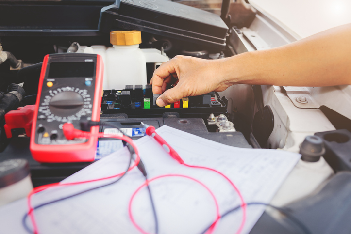
- Test the Switch: Use a multimeter to test if the turn signal switch is functioning correctly. The diagram will indicate which wires should have voltage when the switch is activated.
- Inspect the Bulbs: Visually inspect the bulbs and check their filaments.
- Verify Ground Connections: Ensure the ground connections for the turn signal lights are clean and secure. A poor ground can cause intermittent or no operation.
- Trace the Wires: If you suspect a broken wire, use the diagram to trace the wires and check for damage or loose connections.
By systematically checking each component, guided by the wiring diagram, you can isolate the problem and perform the necessary repairs.
Safety First: Risky Components
Always disconnect the battery before working on any electrical component. This prevents accidental shorts and potential electrical shocks.
Be especially cautious when working with the following:
- Airbag System: Mishandling airbag components can cause them to deploy unexpectedly, resulting in serious injury. Always consult the service manual for proper procedures before working near airbags.
- High-Voltage Systems (Hybrid/Electric Vehicles): These systems operate at hundreds of volts and can be lethal. Never attempt to work on high-voltage components without proper training and equipment.
- Fuel System: Avoid sparks or open flames near fuel lines, as they can ignite flammable vapors.
- Capacitors: Some capacitors can store a charge even after the battery is disconnected. Discharge them properly before handling them.
Remember, if you're uncomfortable working on any electrical component, it's always best to consult a qualified automotive electrician. Your safety is paramount.
Having a detailed wiring diagram specific to your vehicle is a game-changer. It empowers you to understand, diagnose, and repair electrical issues with confidence. While this guide provides a general overview, the specifics of your vehicle's electrical system will be outlined in its unique wiring diagram.
We have the file, and the reader can download the diagram.