Axxess Integrate Output Line Converter Wiring Diagram
An Axxess Integrate Output Line Converter (LOC) is a crucial piece of kit for anyone upgrading their car audio system, especially when dealing with factory radios that lack RCA outputs. Understanding the wiring diagram is paramount for a successful installation, whether you're tackling a repair, upgrading components, or simply expanding your automotive electrical knowledge. This article will break down the Axxess LOC wiring diagram, explaining its purpose, key components, and how to interpret it for practical applications.
Purpose of the Axxess Integrate LOC Wiring Diagram
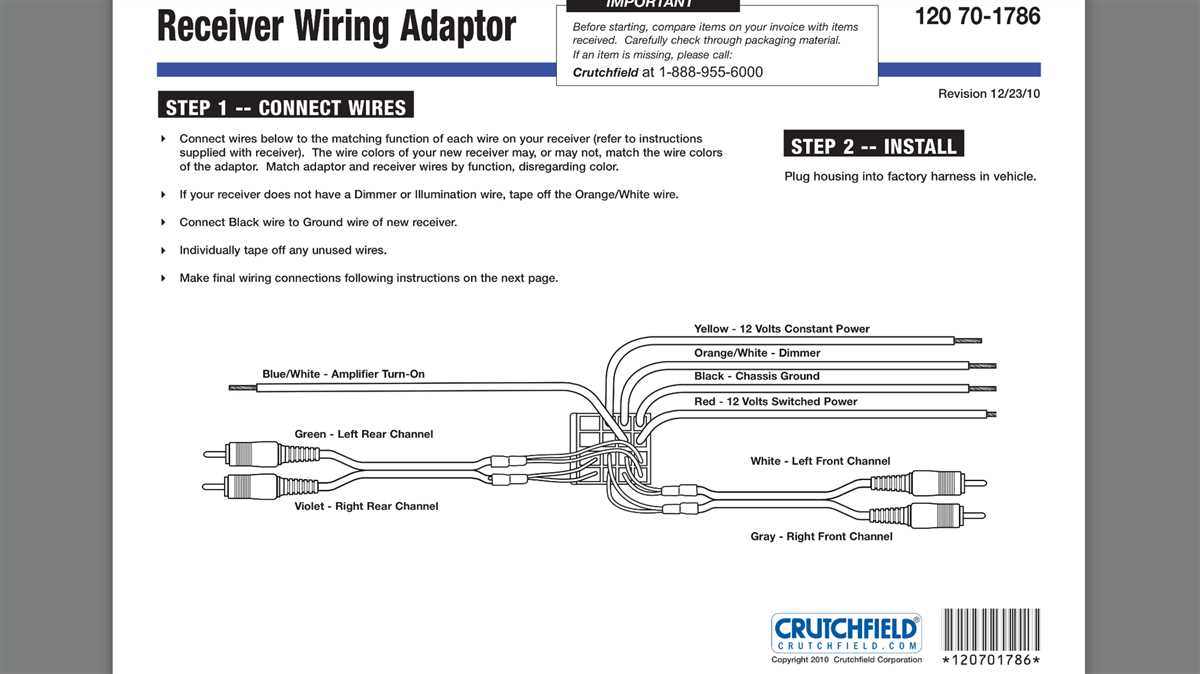
The Axxess LOC wiring diagram serves as a roadmap for connecting the LOC to your factory radio and aftermarket amplifier. Its primary purpose is to illustrate the correct connections between the factory speaker wires (high-level inputs) and the LOC's outputs, which are then connected to your amplifier's RCA inputs (low-level outputs). Without a clear understanding of this diagram, you risk incorrect wiring, which can lead to a blown fuse, a damaged amplifier, or worse, damage to your vehicle's sensitive electronic systems.
Beyond installation, the diagram is invaluable for troubleshooting. If your system isn't producing sound, is distorted, or has grounding issues, the wiring diagram can guide you in systematically checking each connection to isolate the problem.
Key Specs and Main Parts
Before diving into the diagram itself, let's cover the essential components and specifications often associated with Axxess LOCs:
Key Specifications:
- Input Voltage: Typically designed to handle the voltage range of car audio systems (around 12-14.4V DC).
- Output Voltage: Usually adjustable, providing a low-level RCA output (typically around 0-2V RMS).
- Input Impedance: High impedance to avoid loading down the factory radio's speaker outputs.
- Output Impedance: Low impedance to match the input impedance of most aftermarket amplifiers.
- Power Handling: Varies by model, but indicates the maximum wattage the LOC can handle from the factory speaker outputs.
- Channel Configuration: Single channel, two channel, or four channel models.
Main Parts of the LOC (Represented in the Diagram):
- High-Level Inputs: These are the wires that connect to the factory speaker wires. Typically labeled as Left +, Left -, Right +, and Right -.
- Low-Level Outputs (RCA Jacks): These are the RCA connections that connect to your aftermarket amplifier's input. Usually color-coded red (right channel) and white (left channel).
- Power Input (+12V): Connects to a switched +12V source in your vehicle. This is often taken from the radio harness.
- Ground Input (GND): Connects to a solid ground point in your vehicle's chassis. Ensure it’s a clean, rust-free connection.
- Remote Turn-On Wire (REM or Blue Wire): This wire sends a +12V signal to your amplifier, turning it on when the radio is powered on. Some LOCs automatically generate this signal; others require it to be connected to a remote output wire from the radio.
- Gain Adjustment Potentiometers (Pots): Small knobs that allow you to adjust the output signal level to match your amplifier's input sensitivity.
Symbols in the Wiring Diagram
Understanding the symbols in the wiring diagram is vital for proper interpretation. Here's a breakdown of common symbols and their meanings:
- Solid Lines: Represent wires. The thickness may indicate wire gauge (thicker lines = thicker wires).
- Dashed Lines: Often indicate wires that are optional or may not be present in all applications. For example, a dashed remote turn-on wire might indicate that the LOC can sense the audio signal and turn on automatically, or it might be necessary to manually connect it.
- Color Codes: Wires are typically color-coded (e.g., Red = +12V, Black = Ground, White = Left Positive, etc.). The diagram will specify which color corresponds to each function. Note that car manufacturers sometimes vary wire colors, so *always* double-check with a wiring harness diagram specific to your vehicle.
- Ground Symbol ( ): Indicates a connection to the vehicle's chassis ground.
- (+) and (-): Denote positive and negative terminals or wires, respectively.
- RCA Connector Symbol: Represents the RCA jacks for low-level output.
- Potentiometer Symbol ( ): Indicates the location of the gain adjustment knobs.
How It Works: A Deep Dive
The Axxess LOC essentially acts as an interface between your factory radio and your aftermarket amplifier. Factory radios typically don't have RCA outputs because they are designed to power the factory speakers directly. These speaker outputs are high-level signals (higher voltage and current) that cannot be directly connected to an amplifier's low-level RCA inputs.
The LOC takes the high-level speaker signals from your factory radio and converts them into low-level signals suitable for an aftermarket amplifier. This conversion is achieved through a combination of resistors and transformers (or other electronic circuitry) that reduce the voltage and current of the speaker signals. The gain adjustment potentiometers allow you to fine-tune the output signal level to match your amplifier's input sensitivity. Properly setting the gain is crucial for preventing distortion and achieving optimal sound quality.
The remote turn-on function is another important aspect. When your car radio is turned on, the LOC either senses the audio signal or receives a +12V signal from the radio's remote output wire. In turn, it activates its own remote output wire, sending a +12V signal to your amplifier to turn it on. This ensures that your amplifier only draws power when the radio is in use.
Real-World Use and Basic Troubleshooting
Here are some common issues encountered during LOC installation and some basic troubleshooting tips:
- No Sound: Double-check all connections, especially the power and ground wires. Verify that the remote turn-on wire is properly connected and functioning. Use a multimeter to confirm that the LOC is receiving power and that the amplifier is receiving a remote turn-on signal.
- Distorted Sound: This often indicates incorrect gain settings. Start by turning the gain potentiometers on the LOC all the way down, then gradually increase them until the sound is clean and undistorted. Also, check the gain settings on your amplifier.
- Humming or Whining Noise: This is usually caused by a ground loop. Ensure that the LOC and the amplifier are grounded to the same point in the vehicle's chassis. You can also try using a ground loop isolator.
- Blown Fuse: Check for short circuits in the wiring. Inspect all connections to ensure that no bare wires are touching the vehicle's chassis. Use a fuse with the correct amperage rating for the LOC.
- LOC not turning on Amp: Check if the LOC has automatic turn on feature, or must be connected to the remote turn on wire from radio.
Safety Considerations
Working with car audio systems involves handling electrical components, so safety is paramount. Always disconnect the negative terminal of your car's battery before starting any wiring work. This prevents accidental short circuits and potential damage to your vehicle's electrical system.
Be especially cautious when working with the +12V power wire. Ensure that it is properly fused to protect against overcurrent and potential fires. Use properly insulated connectors and wiring to prevent short circuits. Avoid running wires near sharp edges or moving parts that could damage the insulation.
Incorrectly wiring the LOC can damage your factory radio, the LOC itself, or your amplifier. Double-check all connections before applying power. If you are unsure about any aspect of the wiring process, consult a professional car audio installer.
Disclaimer: This guide is for informational purposes only. Car audio systems are complex, and improper installation can lead to damage. Always consult a qualified professional if you are unsure about any aspect of the installation process.
We have the detailed Axxess Integrate Output Line Converter wiring diagram file. Contact us to request a download link.