
Basic Air Conditioning System Diagram
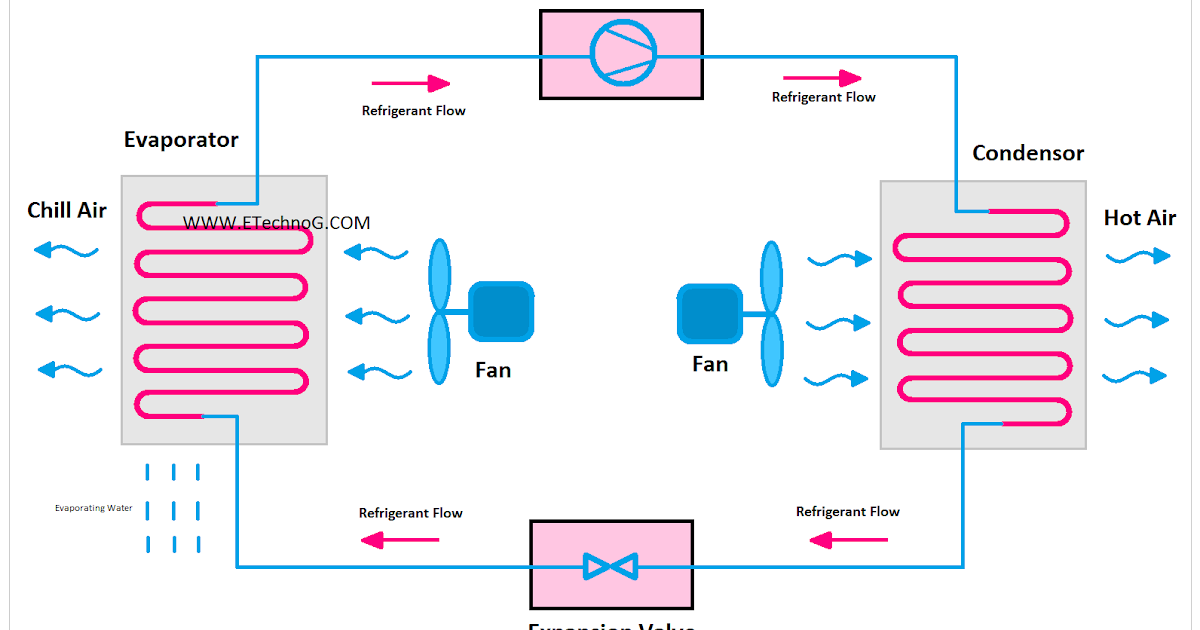
Alright folks, let's dive into the fascinating world of automotive air conditioning. Understanding your AC system isn't just about staying cool; it's a powerful tool for diagnosing problems, performing basic repairs, and even planning modifications. This article will break down the basic air conditioning system diagram, equipping you with the knowledge to tackle common issues and understand the intricate workings of your car's climate control.
Why Bother with the AC Diagram?
Think of the AC diagram as the roadmap to your cooling system. It allows you to:
- Diagnose problems effectively: Pinpointing the source of a leak, identifying a faulty component, or understanding pressure imbalances becomes much easier with a visual guide.
- Perform basic repairs: Replacing a refrigerant line, diagnosing a compressor issue, or checking the receiver-drier become less daunting tasks.
- Plan modifications: Upgrading your system for better performance, integrating aftermarket components, or customizing the cooling capacity require a solid understanding of the existing setup.
- Understand the system: Gain a deeper appreciation for the engineering that keeps you comfortable on those scorching summer days.
Key Specs and Main Parts
Before we dissect the diagram, let's identify the major players in the AC system. These components are interconnected and work in a carefully orchestrated dance to transfer heat out of your vehicle.
The Compressor
The compressor is the heart of the system, driven by the engine via a belt. Its job is to compress the refrigerant gas, raising its pressure and temperature. This high-pressure, high-temperature gas then flows to the condenser.
The Condenser
Located typically in front of the radiator, the condenser resembles a small radiator. It allows the high-pressure, hot refrigerant gas to cool down and condense into a high-pressure, warm liquid. Think of it as releasing the heat collected from inside the car.
The Receiver-Drier (or Accumulator)
The receiver-drier (found in systems with a thermal expansion valve, TXV) or accumulator (used with orifice tube systems) acts as a filter and storage reservoir for the refrigerant. It removes moisture and contaminants from the refrigerant and stores excess liquid refrigerant. The receiver-drier contains a desiccant to absorb moisture. The accumulator, located on the low-pressure side, protects the compressor from liquid refrigerant.
The Expansion Valve (or Orifice Tube)
The expansion valve (TXV) or orifice tube is the metering device that regulates the flow of refrigerant into the evaporator. The TXV senses evaporator temperature and adjusts the refrigerant flow accordingly. The orifice tube is a fixed-size restrictor that controls refrigerant flow; in systems with an orifice tube, a cycling switch is used to cycle the compressor on and off to regulate evaporator temperature.
The Evaporator
Located inside the dashboard, the evaporator is where the refrigerant absorbs heat from the cabin air, cooling it down. The low-pressure, cold liquid refrigerant evaporates into a low-pressure, cold gas, which then returns to the compressor to repeat the cycle.
Decoding the Diagram: Symbols and Conventions
AC system diagrams use a standardized set of symbols to represent different components and lines. Here's a breakdown of common conventions:
- Lines: Represent refrigerant lines. Solid lines typically indicate high-pressure lines, while dashed lines indicate low-pressure lines.
- Arrows: Show the direction of refrigerant flow.
- Color Coding: Sometimes used to differentiate between high-pressure (often red) and low-pressure (often blue) lines. This isn't universal, so always refer to the diagram's legend.
- Component Symbols: Each component has a specific symbol. Common examples include:
- Compressor: A circle with internal vanes or a piston symbol.
- Condenser: A zigzag line with fins.
- Receiver-Drier/Accumulator: A cylinder with or without a desiccant symbol (a small bag).
- Expansion Valve: A valve symbol with a sensing bulb.
- Orifice Tube: A small restrictor symbol.
- Evaporator: A zigzag line with fins, often enclosed in a box representing the air handler.
- Electrical Components: Relays, switches, and sensors are depicted using standard electrical symbols.
Pay close attention to the diagram's legend or key. This will provide a comprehensive explanation of all the symbols and conventions used.
How It Works: The Refrigeration Cycle
The air conditioning system operates on a closed-loop refrigeration cycle. Here's a simplified explanation:
- Compression: The compressor takes in low-pressure, low-temperature refrigerant gas and compresses it into a high-pressure, high-temperature gas.
- Condensation: The hot, high-pressure gas flows to the condenser, where it releases heat to the outside air and condenses into a high-pressure, warm liquid.
- Metering: The high-pressure liquid refrigerant passes through the expansion valve or orifice tube, causing a pressure drop and a corresponding temperature drop. This creates a low-pressure, cold liquid.
- Evaporation: The cold, low-pressure liquid refrigerant enters the evaporator, where it absorbs heat from the cabin air, causing it to evaporate into a low-pressure, cold gas. This process cools the air that blows into the cabin.
- Return: The low-pressure, cold gas returns to the compressor, completing the cycle.
Real-World Use: Basic Troubleshooting
Understanding the AC diagram can help you troubleshoot common problems. Here are a few examples:
- No Cold Air: Check the compressor clutch. Is it engaging? If not, check the electrical connections, relay, and pressure switches. A low refrigerant charge can prevent the compressor from engaging.
- Weak Airflow: Inspect the blower motor and resistor. Check for obstructions in the air ducts or a clogged cabin air filter.
- Leaking Refrigerant: Look for oily residue around fittings, hoses, and components. This is a telltale sign of a refrigerant leak. Use a UV dye and light to pinpoint the source.
- Strange Noises: Grinding or squealing noises could indicate a failing compressor or a worn belt.
Remember to use a manifold gauge set to check the high and low side pressures. These readings can provide valuable clues about the system's performance. Consult a service manual for the correct pressure readings for your vehicle.
Safety First: High-Pressure Hazards
The AC system contains high-pressure refrigerant, which can be dangerous if handled improperly.
Never disconnect refrigerant lines without properly evacuating the system using a refrigerant recovery machine. Releasing refrigerant into the atmosphere is illegal and harmful to the environment.
The compressor also contains high-pressure oil. Be cautious when working around the compressor and wear appropriate safety gear, including eye protection and gloves.
Conclusion
By understanding the basic air conditioning system diagram and the principles of the refrigeration cycle, you can gain valuable insights into your car's climate control system. This knowledge empowers you to diagnose problems, perform basic repairs, and make informed decisions about modifications. Remember to prioritize safety and consult a qualified technician when dealing with complex issues or high-pressure components.
Now that you have completed reading, we have the system diagram file, you can download it and use it for your repair.