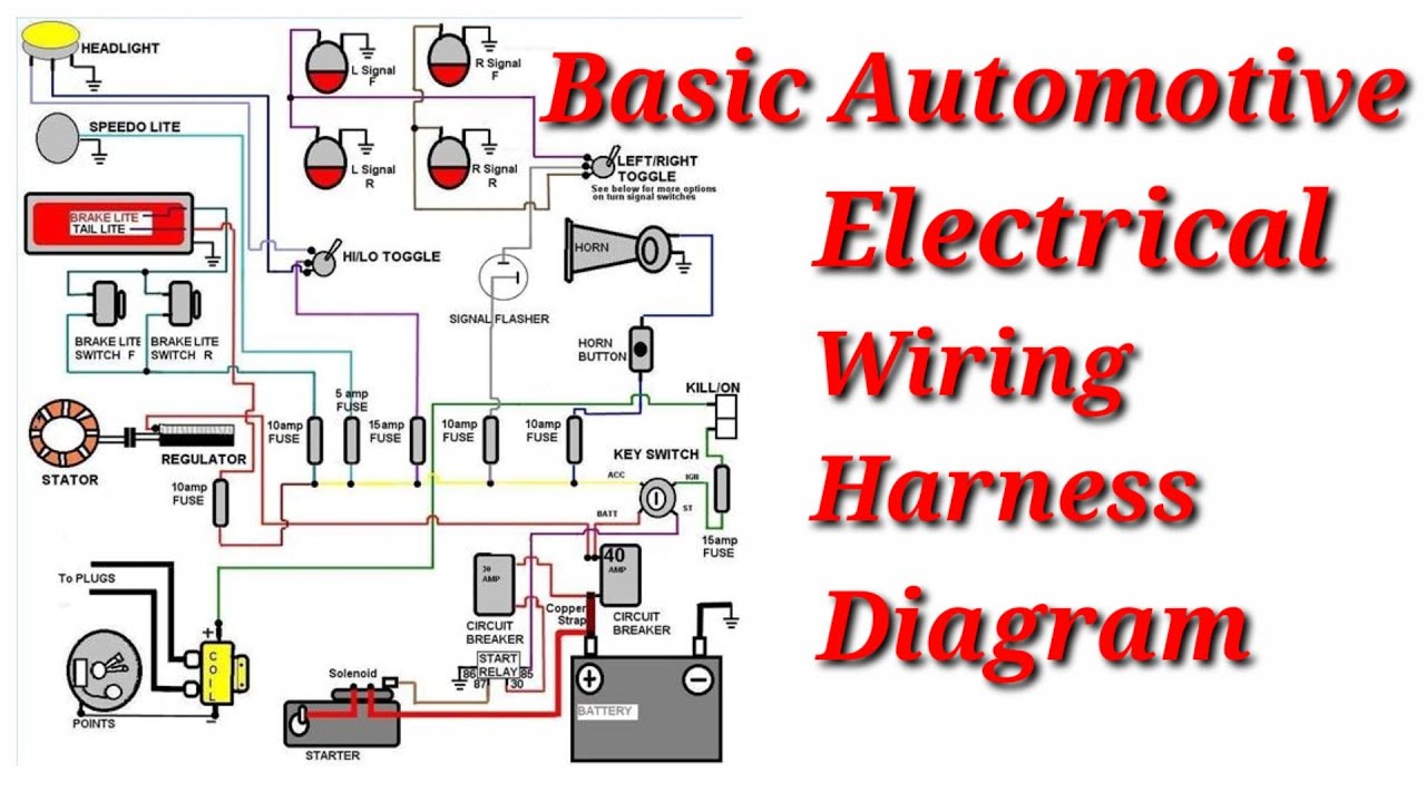
Basic Auto Electrical Wiring Diagram
Understanding your car's electrical system can feel like navigating a labyrinth. However, with a good auto electrical wiring diagram, even complex circuits become manageable. This guide will walk you through the essentials, empowering you to diagnose problems, perform modifications, and even tackle repairs with confidence. We'll cover everything from the basic components to reading the symbols and applying that knowledge to real-world scenarios. Think of this as your roadmap to automotive electrical expertise.
Purpose of an Auto Electrical Wiring Diagram
Why bother learning to read these diagrams? The answer is multifaceted. A wiring diagram is essential for:
- Diagnostics and Repair: When a circuit malfunctions, the diagram helps you trace the fault systematically. You can pinpoint the problem area, check continuity, and verify voltage levels.
- Modifications and Upgrades: Want to install a new stereo, auxiliary lights, or a performance chip? The wiring diagram shows you where to tap into the existing circuits safely and effectively.
- Understanding Your Vehicle: Learning to read the diagram grants a deeper comprehension of how your car's electrical components interact. This knowledge is invaluable for preventative maintenance and identifying potential issues early on.
- Preventing Electrical Fires: Tampering with electrical systems without proper understanding can lead to short circuits and fires. The diagram helps you ensure that any modifications you make are safe and don't overload circuits.
Key Specs and Main Parts of the Electrical System
Before diving into the diagrams, let's review the primary components of a typical automotive electrical system:
- Battery: The heart of the system, providing the initial power (typically 12V DC).
- Alternator: Recharges the battery while the engine is running and provides power to most electrical components.
- Starter: An electric motor that cranks the engine for starting.
- Fuses and Circuit Breakers: Protective devices that interrupt the current flow in case of a short circuit or overload. Fuses are sacrificial; they blow and must be replaced. Circuit breakers can reset.
- Relays: Electrically operated switches that allow a small current to control a larger current circuit. Used for components like headlights, horns, and fuel pumps.
- Switches: Manual or electronic devices that open or close circuits (e.g., headlight switch, ignition switch).
- Wiring Harness: A bundle of wires that connects all the electrical components.
- ECU (Engine Control Unit)/PCM (Powertrain Control Module): The car's computer, controlling engine functions and other systems.
- Sensors: Devices that monitor various parameters (e.g., temperature, pressure, speed) and send signals to the ECU.
- Actuators: Devices that perform actions based on signals from the ECU (e.g., fuel injectors, solenoids).
- Grounds: Critical connection points that provide a return path for current to the battery. Poor grounds can cause all sorts of electrical problems.
Understanding Wiring Diagram Symbols
Wiring diagrams use a standardized set of symbols to represent electrical components and connections. Let's break down the most common ones:
Lines
- Solid Lines: Represent wires carrying electrical current.
- Dashed Lines: Often indicate shielded wires or wires that are part of a data bus (like CAN bus).
- Line Thickness: Generally doesn't represent wire gauge in basic diagrams but in some advanced diagrams, thicker lines may indicate higher current capacity.
- Arrows: Show the direction of current flow (though this is often implied).
Colors
Wire colors are crucial for identification. Diagrams usually use abbreviations for colors. Here's a common list:
- BK: Black (Ground)
- RD: Red (Power)
- BL: Blue
- GN: Green
- WT: White
- YL: Yellow
- OR: Orange
- BR: Brown
- VT: Violet
- GY: Gray
Icons
Icons represent the electrical components themselves. Some common examples include:
- Battery: A series of short and long parallel lines.
- Resistor: A zig-zag line.
- Capacitor: Two parallel lines.
- Inductor/Coil: A coiled line.
- Diode: A triangle pointing to a line.
- Fuse: A squiggly line inside a rectangle or circle.
- Switch: A line connecting to another line, with an arrow indicating the direction of switching.
- Relay: A coil and a set of switch contacts.
- Ground: A series of downward-pointing lines, resembling an upside-down tree.
- Motor: A circle with an "M" inside.
- Lamp/Bulb: A circle with an "X" inside.
Note: There can be variations in symbols, so always refer to the diagram's legend or key.
How It Works: Reading the Diagram
Let's imagine a simplified circuit: the headlights. The diagram will show the battery connected to the ignition switch. From the ignition switch, a wire runs to the headlight switch. The headlight switch controls the high beam and low beam relays. These relays then send power to the headlights themselves, with a ground connection completing the circuit.
To trace the circuit, start at the battery symbol. Follow the line (representing the wire) to the next component (the ignition switch). Notice the wire color abbreviation (e.g., "RD/WT" for red with a white stripe). Keep following the lines and components until you reach the end of the circuit (the headlights and the ground). This process allows you to understand the flow of electricity and identify potential points of failure.
Many diagrams will also include information like wire gauge, connector locations, and component identification numbers. These details are invaluable for accurate troubleshooting and repair.
Real-World Use: Basic Troubleshooting Tips
Now, let's put this knowledge into practice. Suppose your headlights aren't working. Here's how you might use the wiring diagram:
- Consult the Diagram: Locate the headlight circuit diagram for your specific vehicle.
- Check the Fuses: Identify the fuse(s) related to the headlights. Use a multimeter to test for continuity. If a fuse is blown, replace it with one of the correct amperage rating.
- Inspect the Relays: If the fuse is good, check the headlight relays. You can test them by swapping them with a known good relay of the same type or by using a multimeter to check for continuity and voltage.
- Test the Switch: Use a multimeter to check if the headlight switch is sending power to the relays when activated.
- Check the Grounds: Inspect the ground connections for the headlights. Clean and tighten any corroded or loose ground connections. A bad ground is a very common cause of electrical problems.
- Trace the Wiring: If all else fails, use the wiring diagram to trace the wires between the components, looking for breaks, shorts, or corrosion.
Important: Always disconnect the battery's negative terminal before working on the electrical system to prevent accidental shorts.
Safety Considerations
Working with automotive electrical systems can be dangerous. Here are some key safety precautions:
- Disconnect the Battery: As mentioned before, disconnect the negative terminal before starting any electrical work.
- Avoid Short Circuits: Be careful not to create short circuits by accidentally touching wires to ground.
- Work in a Well-Ventilated Area: Battery acid and other automotive fluids can release harmful fumes.
- Use Proper Tools: Use insulated tools designed for electrical work.
- Handle Airbags Carefully: Airbag circuits are particularly sensitive. Consult a professional if you need to work on or near them. Airbags are extremely dangerous and can cause serious injury if deployed accidentally.
- High-Voltage Components: Some components, like the ignition system, can generate high voltages. Be extremely cautious when working around these areas.
Remember: If you're uncomfortable working with electrical systems, consult a qualified automotive electrician.
We have a basic auto electrical wiring diagram file available for download. This example can help you further understand the concepts discussed and serve as a starting point for your learning journey.