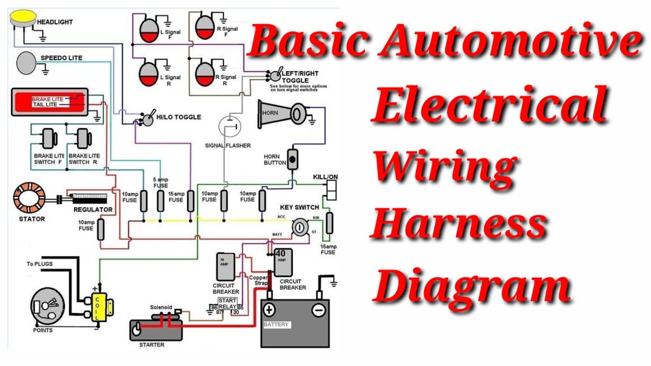
Basic Automotive Electrical Wiring Diagram
Understanding your vehicle's electrical system can seem like navigating a complex maze, but it doesn't have to be. A crucial tool for this journey is the automotive electrical wiring diagram. This article will demystify these diagrams, empowering you to diagnose problems, perform modifications, and gain a deeper understanding of your car's inner workings.
Purpose of Automotive Electrical Wiring Diagrams
Why bother learning about these diagrams? Well, they serve several critical purposes:
- Troubleshooting: Pinpointing the source of electrical faults, from a malfunctioning headlight to a complex engine management issue.
- Repairs: Guiding you through component replacement and wire repairs, ensuring correct connections.
- Modifications: Safely adding aftermarket accessories like lighting, sound systems, or performance enhancements.
- Learning: Gaining a fundamental understanding of how your car's electrical system is designed and operates.
Without a diagram, you're essentially guessing. With one, you have a roadmap to diagnose, repair, and modify with confidence. Imagine trying to rewire a radio without knowing which wire goes where – a diagram eliminates the guesswork and minimizes the risk of short circuits or damage to sensitive components.
Key Specs and Main Parts of a Wiring Diagram
An automotive electrical wiring diagram is a simplified, visual representation of the electrical circuits within a vehicle. It shows the various components, their interconnections, and the flow of electricity. Here's what you need to know:
Power Source
The starting point is usually the battery. Look for the symbol representing the battery, typically a series of parallel lines (long and short) indicating positive (+) and negative (-). The diagram will show how power is distributed from the battery to various circuits through fuses, relays, and switches.
Fuses and Circuit Breakers
These are critical safety devices designed to protect circuits from overcurrent. A fuse is represented by a squiggly line inside a rectangle or a simple rectangle. A circuit breaker often has a similar symbol but may include a small switch or lever to indicate reset capability.
Relays
Relays are electromagnetic switches that allow a low-current circuit to control a high-current circuit. They're often used to switch on headlights, fuel pumps, and other power-hungry components. The symbol usually includes a coil (a looped wire) and a switch that is either normally open (NO) or normally closed (NC).
Switches
Switches control the flow of electricity in a circuit. Common types include toggle switches, push-button switches, and rotary switches. The symbols vary depending on the type, but they generally show a break in the circuit that can be opened or closed.
Wires and Connectors
Wires are represented by lines connecting the various components. Connectors are points where wires can be easily disconnected, often indicated by a circle or square with a line pointing outwards.
Ground
Ground is the return path for electricity, typically the vehicle's chassis. Ground symbols vary but often resemble a downward-pointing triangle or a series of horizontal lines.
Loads
Loads are the components that consume electricity, such as lights, motors, sensors, and actuators. Their symbols vary depending on the specific component.
Understanding Wiring Diagram Symbols
Decoding the symbols used in a wiring diagram is essential for accurate interpretation. Let's break down the key elements:
Lines
Lines represent wires. A solid line indicates a direct connection. Dashed lines may represent a shielded wire or a connection that is not always present (e.g., optional equipment).
Colors
Wire colors are typically indicated by abbreviations. For example:
- BK: Black
- RD: Red
- BL: Blue
- GN: Green
- WT: White
- YL: Yellow
Icons
Icons represent specific components. Here are some common examples:
- Battery: A series of long and short parallel lines.
- Resistor: A zigzag line.
- Capacitor: Two parallel lines.
- Diode: A triangle pointing to a line.
- Light Bulb: A circle with an "X" inside.
- Motor: A circle with an "M" inside.
How It Works: Tracing a Circuit
The key to using a wiring diagram is to trace the flow of electricity through the circuit you're interested in. Start at the power source (battery) and follow the wire through any fuses, switches, relays, and finally to the load. Pay attention to the wire colors and connector locations. By tracing the circuit, you can identify potential points of failure, such as a blown fuse, a faulty switch, or a broken wire.
For instance, imagine you have a non-functioning headlight. Start by finding the headlight circuit in the diagram. Trace the power from the battery, through the fuse box, the headlight switch, the relay (if present), and finally to the headlight itself. Use a multimeter to check for voltage at each point along the way. If you find voltage at the fuse but not at the headlight switch, the problem likely lies between those two points.
Real-World Use: Basic Troubleshooting Tips
Here are a few practical tips for using wiring diagrams for troubleshooting:
- Start with the obvious: Check fuses and bulbs first. A blown fuse is often the simplest explanation for a malfunctioning circuit.
- Use a multimeter: A multimeter is your best friend for electrical troubleshooting. Use it to check for voltage, continuity, and resistance.
- Isolate the problem: Disconnect components one at a time to isolate the faulty section of the circuit.
- Check grounds: A poor ground connection can cause all sorts of problems. Make sure all ground connections are clean and secure.
- Refer to the diagram: Keep the wiring diagram handy and refer to it frequently.
Example: If your turn signal isn't working, the diagram will show you the location of the turn signal flasher relay, the turn signal switch, and the wiring to each turn signal bulb. You can then use a multimeter to test these components and trace the circuit to find the fault.
Safety Precautions
Working with automotive electrical systems can be dangerous. Here are some important safety precautions:
- Disconnect the battery: Always disconnect the negative terminal of the battery before working on any electrical components. This prevents accidental short circuits and potential electric shock.
- Identify high-risk components: Be aware of components that carry high voltage or current, such as the ignition system and the starter motor. Avoid touching these components while the engine is running or the ignition is on.
- Use insulated tools: Use tools with insulated handles to protect yourself from electric shock.
- Work in a well-lit area: Adequate lighting is essential for seeing what you're doing and avoiding mistakes.
- Consult a professional: If you're unsure about any aspect of the electrical system, consult a qualified mechanic.
Especially be careful around the ignition system – it generates thousands of volts, even with the engine off. Capacitors can also store a charge even after the battery is disconnected.
Remember, safety is paramount. If you're uncomfortable working with electrical systems, it's always best to leave it to a professional.
We have a sample automotive electrical wiring diagram available for download. It provides a visual aid to understanding the principles discussed here. With practice and patience, you can master the art of interpreting wiring diagrams and confidently tackle a wide range of automotive electrical tasks.