
Basic Brake Light Switch Wiring Diagram
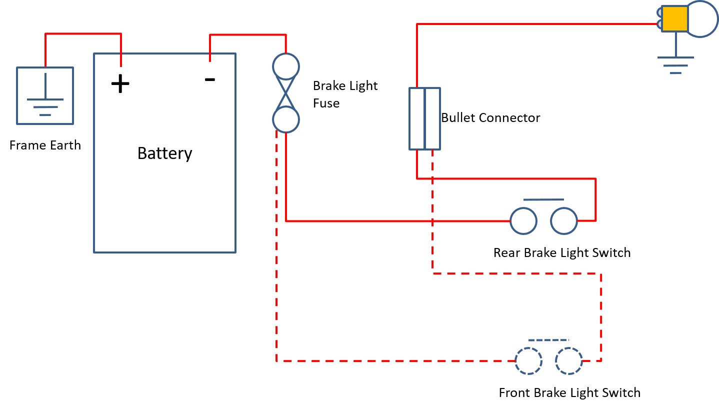
Understanding the basic brake light switch wiring diagram is crucial for anyone working on automotive electrical systems, whether you're tackling a simple repair, customizing your vehicle, or just expanding your knowledge of how things work. This guide will walk you through the key components, symbols, and functions of a typical brake light circuit, providing you with the knowledge needed to diagnose and troubleshoot common issues.
Purpose and Importance
Why bother learning about this seemingly small part of your car's electrical system? Well, functional brake lights are essential for safety. A faulty brake light switch can lead to non-operational brake lights, which increases the risk of accidents, especially in stop-and-go traffic or low-visibility conditions. Beyond safety, understanding this circuit is a great stepping stone to understanding more complex automotive electrical systems. This knowledge is invaluable for:
- Troubleshooting Brake Light Issues: Identifying and fixing problems with your brake lights quickly and efficiently.
- DIY Repairs: Replacing a faulty brake light switch yourself, saving money on labor costs.
- Electrical System Understanding: Gaining a better grasp of how automotive electrical circuits work.
- Customization: Integrating aftermarket accessories that rely on brake light signals (e.g., custom lighting, performance modifications).
Key Specs and Main Parts
Let's break down the components involved in a basic brake light switch circuit. While specific implementations can vary slightly between makes and models, the core elements remain consistent:
- Battery: The heart of the system, providing the direct current (DC) electrical power. Typically a 12V system in most vehicles.
- Fuse: A sacrificial device designed to protect the circuit from overcurrent. It consists of a thin wire that melts and breaks the circuit if excessive current flows through it. This prevents damage to other components. The amperage rating of the fuse is critical; using a higher-rated fuse can lead to serious damage or even fire.
- Brake Light Switch: This is the key component. It's typically located near the brake pedal. When the brake pedal is pressed, the switch closes, completing the circuit and allowing current to flow to the brake lights. When the pedal is released, the switch opens, interrupting the circuit and turning off the brake lights. There are normally open (NO) and normally closed (NC) switch types. Brake light switches are *usually* NO type.
- Brake Lights (Bulbs or LEDs): These are the load in the circuit. They illuminate when the circuit is complete, signaling to other drivers that you are braking. Bulbs are rated in watts (power consumption), while LEDs are often rated in lumens (brightness).
- Wiring: The conductive pathways that connect all the components together. Automotive wiring is typically stranded copper wire, insulated with PVC or other suitable materials. Wire gauge (thickness) is crucial; thicker wires can handle higher currents without overheating. Common gauges in automotive applications include 18 AWG, 16 AWG, 14 AWG, and 12 AWG.
- Ground Connection: Provides a return path for the current to the battery, completing the circuit. A good, clean ground connection is essential for proper circuit operation. Ground points are often located on the vehicle's chassis or frame.
Symbols and Diagram Conventions
Understanding the symbols used in electrical wiring diagrams is crucial for interpreting them correctly.
- Straight Lines: Represent wires. Thicker lines may sometimes (but not always) indicate heavier gauge wires.
- Dashed Lines: Often indicate wires that are part of a harness or are shielded.
- Circles: Can represent various components, depending on what's inside (e.g., a circle with a filament symbol inside represents a light bulb).
- Squares/Rectangles: Often used to represent control modules or other electronic components.
- Switches: Represented by a break in the line, with a symbol indicating the switch type (e.g., normally open, normally closed).
- Ground Symbol: Usually looks like a series of descending horizontal lines, indicating a connection to ground (the vehicle's chassis).
- Fuse Symbol: A zig-zag line inside a rectangle.
Wire Colors: Wire colors are standardized to some extent, but can vary between manufacturers and even between models within the same brand. Common colors include red (typically for power), black (typically for ground), and various other colors for signal wires. Always refer to the specific wiring diagram for your vehicle to confirm wire colors. Wiring diagrams often include a legend indicating what each color represents.
How It Works
The basic operation of the brake light switch circuit is straightforward:
- The battery provides power to the circuit.
- The power flows through the fuse, which protects the circuit from overcurrent.
- The power then reaches the brake light switch.
- When the brake pedal is not pressed, the brake light switch is open, and no current flows.
- When the brake pedal is pressed, the brake light switch closes, completing the circuit.
- Current flows through the switch to the brake lights.
- The brake lights illuminate, signaling to other drivers that you are braking.
- The current then flows through the ground connection, returning to the battery, completing the circuit.
Real-World Use: Basic Troubleshooting
Here are some common issues and how to troubleshoot them using your understanding of the wiring diagram:
- No Brake Lights:
- Check the Fuse: Use a multimeter to test for continuity across the fuse. If it's blown, replace it with a fuse of the correct amperage rating.
- Test the Brake Light Switch: Use a multimeter to check for voltage at the switch when the brake pedal is pressed. If there's no voltage, the switch is likely faulty.
- Check the Bulbs: Visually inspect the bulbs for burned filaments. Replace any faulty bulbs.
- Check the Ground Connection: Ensure the ground connection is clean and secure. Corrosion can prevent proper grounding.
- Brake Lights Stay On:
- Stuck Brake Light Switch: The switch might be physically stuck in the closed position. Try manually manipulating the switch.
- Switch Adjustment: The switch might be misadjusted, causing it to remain closed even when the brake pedal is released. Adjust the switch according to the vehicle's service manual.
- Wiring Short: A short circuit in the wiring can cause the brake lights to stay on. Inspect the wiring for damage or chafing.
- One Brake Light Works, the Other Doesn't:
- Bulb: Most likely, the bulb is burned out.
- Wiring: Check the wiring and connector for the non-working light.
Safety Precautions
Working with automotive electrical systems can be dangerous. Here are some essential safety precautions:
- Disconnect the Battery: Always disconnect the negative battery terminal before working on any electrical circuit. This prevents accidental shorts and electrical shocks.
- Use Proper Tools: Use insulated tools designed for automotive electrical work.
- Avoid Water: Never work on electrical systems in wet conditions.
- Replace Fuses with the Correct Rating: Using a fuse with a higher amperage rating than specified can lead to serious damage or fire.
- Be Careful with Wiring: Avoid damaging or chafing wires. Damaged insulation can lead to short circuits.
By understanding the basic brake light switch wiring diagram, you are empowering yourself to handle basic automotive electrical repairs and modifications safely and effectively. Remember to always consult your vehicle's specific service manual for detailed information and diagrams.
We have a downloadable version of a sample brake light switch wiring diagram available for your convenience. Feel free to request it!