
Basic Car Electrical Wiring Diagrams
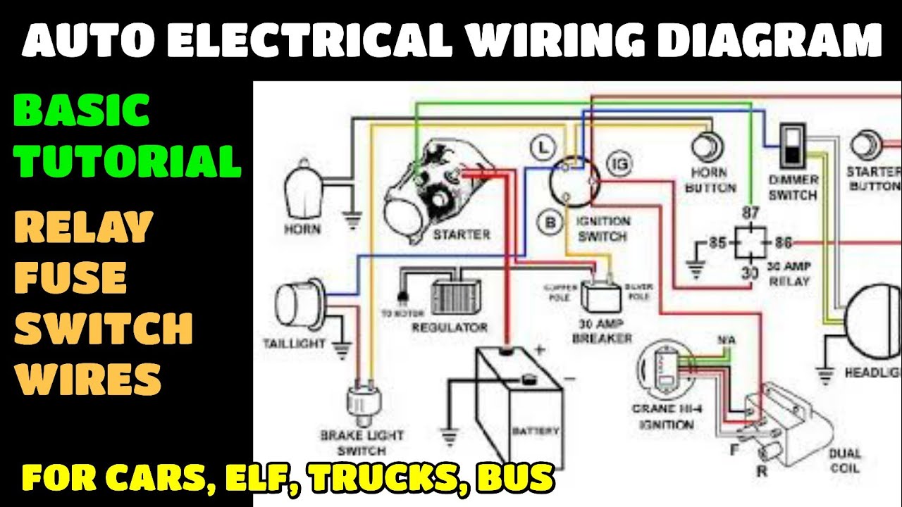
Understanding your car's electrical system can feel like deciphering a complex code, but with a good wiring diagram, it becomes manageable, even empowering. This article will break down the essentials of basic car electrical wiring diagrams, equipping you with the knowledge to tackle repairs, modifications, and a deeper understanding of your vehicle. We'll focus on common systems and diagrams you're likely to encounter. Remember, automotive electrical work requires precision and caution.
Purpose: Why Bother with Wiring Diagrams?
A wiring diagram is essentially a roadmap of your car's electrical system. It shows all the components, their connections, and how they interact. Why is this important? Consider these scenarios:
- Troubleshooting Electrical Issues: When a circuit fails (lights don’t work, sensors malfunction, etc.), a diagram allows you to trace the problem back to its source. Is the issue a faulty component, a broken wire, or a bad connection? The diagram guides you.
- Performing Modifications: Adding aftermarket accessories (stereo systems, alarms, lighting) requires tapping into existing circuits. A wiring diagram ensures you're connecting to the correct wires and not overloading any circuits.
- Understanding Vehicle Systems: Simply put, knowledge is power. A diagram lets you understand how different systems (e.g., the ignition system, charging system, or lighting system) are wired and how they function.
- Performing Repairs: Whether you are replacing a worn-out wire or repairing a damaged connector, a wiring diagram can help you ensure you are doing it correctly.
Key Specs and Main Parts of a Wiring Diagram
Before diving into the diagram itself, let's cover some key terminology and components you'll encounter. Keep in mind that specific nomenclature can vary slightly between manufacturers, but the underlying principles remain the same.
- Components: These are the actual electrical parts within the circuit, such as:
- Battery: The primary power source (typically 12V DC).
- Fuses: Safety devices that protect circuits from overcurrent (excessive amperage).
- Relays: Electrically operated switches that control high-current circuits using a low-current control signal.
- Switches: Devices that open or close a circuit.
- Sensors: Devices that measure physical parameters (temperature, pressure, position) and convert them into electrical signals.
- Actuators: Devices that convert electrical signals into mechanical motion (motors, solenoids).
- ECU (Engine Control Unit): The car's computer that controls various engine functions. Increasingly, other control units exist for transmission, brakes, body control, etc.
- Wiring Harnesses: Bundles of wires that connect different parts of the electrical system.
- Voltage (V): The electrical potential difference; in a car, this is typically 12 volts (VDC).
- Current (Amps - A): The rate of flow of electrical charge. Fuses are rated in amps.
- Resistance (Ohms - Ω): The opposition to the flow of current. This is crucial in understanding the function of some sensors.
- Ground: The reference point (usually the vehicle's chassis) to which all voltages are measured. A good ground connection is vital for proper operation.
Understanding Wiring Diagram Symbols
Wiring diagrams use standardized symbols to represent components and connections. Learning these symbols is key to interpreting the diagram. Here's a breakdown of common symbols:
- Lines: Represent wires. Thicker lines may indicate wires that carry higher currents.
- Color Coding: Wires are typically color-coded to help identify them within the harness. The diagram will include a color code legend (e.g., BLU = Blue, GRN = Green, RED = Red). Always refer to the legend.
- Component Symbols: These are stylized representations of the components themselves. Common examples include:
- Battery: Often shown as a series of short and long parallel lines.
- Fuse: A zigzag line within a rectangle or circle.
- Relay: A coil symbol (representing the electromagnet) and a switch symbol.
- Resistor: A zigzag line.
- Ground: Three horizontal lines, decreasing in size.
- Switch: A line that opens or closes a connection.
- Connectors: Shown as circles or rectangles where wires connect. These often have identifying numbers or letters.
- Splices: Points where multiple wires are joined together.
How It Works: Tracing a Circuit
The key to understanding a wiring diagram is to be able to trace a circuit. Here's the general process:
- Identify the Power Source: Usually the battery. Trace the positive (+) side of the battery.
- Follow the Wire: Track the wire from the power source through fuses, switches, relays, and other components.
- Identify the Load: This is the component that uses the power (e.g., a light bulb, a motor).
- Trace the Ground Path: After the load, the wire must return to the negative (-) side of the battery through a ground connection.
For example, let's consider a simple headlight circuit. The circuit starts at the battery (+), goes through a fuse (to protect against overcurrent), then to the headlight switch. When the switch is turned on, it allows current to flow to the headlight bulb. From the bulb, the current flows to a ground connection, completing the circuit back to the battery (-).
Real-World Use: Basic Troubleshooting Tips
Wiring diagrams are invaluable for troubleshooting electrical problems. Here are some basic tips:
- Start Simple: If a system isn't working, start by checking the fuse for that circuit. A blown fuse is often the easiest fix.
- Use a Multimeter: A multimeter is your best friend for electrical troubleshooting. Use it to check for voltage, continuity (a complete circuit), and resistance.
- Check for Voltage Drops: A voltage drop across a component or connection indicates resistance, which can cause problems.
- Inspect Connectors: Check for corroded, loose, or damaged connectors. Clean and tighten connections as needed.
- Test Grounds: Make sure the ground connections are clean and secure. A bad ground can cause all sorts of weird electrical problems.
- Divide and Conquer: Break down the circuit into smaller sections to isolate the problem. If the headlight on the driver's side doesn't work, but the passenger's side does, focus on the wiring and components specific to the driver's side headlight.
Safety First!
Working with automotive electrical systems can be dangerous. Always follow these safety precautions:
- Disconnect the Battery: Before working on any electrical circuit, disconnect the negative (-) battery terminal. This prevents accidental shorts and shocks.
- Work in a Well-Ventilated Area: Batteries can produce explosive gases.
- Use Proper Tools: Use insulated tools designed for electrical work.
- Be Careful with Airbags: Airbags are triggered by electrical signals. Consult your vehicle's service manual for specific instructions on disabling the airbag system before working near airbag components. Accidental deployment can cause serious injury.
- High Current Circuits: Be especially careful when working with circuits that carry high currents (e.g., starter motor circuits, alternator circuits). Short circuits in these areas can cause fires.
Warning: Always disconnect the battery negative terminal before commencing any electrical work. Exercise extreme caution with the airbag system to avoid accidental deployment.
Conclusion
This article provides a foundation for understanding basic car electrical wiring diagrams. It's a skill that empowers you to maintain, repair, and customize your vehicle with confidence. Remember to start simple, use the right tools, and always prioritize safety. With some practice, you'll be able to read wiring diagrams like a pro. And, remember, automotive electrical systems can be complex, if you're not comfortable working on them, it's always best to consult a qualified mechanic.
We have a sample wiring diagram available for download. This diagram covers the basic headlight circuit of a common car model and it provides a great starting point for you to practice identifying components, tracing circuits, and applying the concepts discussed in this article.