
Basic Wiring Diagram For Light Switch
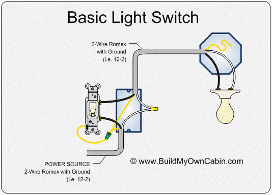
Alright, let's dive into the nitty-gritty of a basic light switch wiring diagram. Whether you're troubleshooting a flickering headlight, adding auxiliary lighting, or simply expanding your automotive electrical understanding, knowing how a simple light switch circuit works is absolutely fundamental. This isn't just about swapping parts; it's about understanding the flow of electricity and gaining the confidence to tackle more complex automotive electrical projects. We'll break down the diagram, the components, and how to interpret it, giving you the tools to diagnose and repair issues with confidence.
Purpose: Why This Matters
Understanding a light switch wiring diagram is crucial for a few key reasons:
- Repairs and Diagnostics: When a light isn't working, this knowledge allows you to systematically trace the circuit, identify the faulty component (switch, wiring, or the light itself), and fix it.
- Customization and Modification: Adding aftermarket lights, fog lights, or any electrical accessory requires understanding how to safely integrate them into your car's electrical system. A light switch circuit is often the foundation for these additions.
- Electrical Understanding: This is a building block. Understanding basic circuits empowers you to troubleshoot and modify other electrical systems in your car. Think wipers, horns, or even basic sensor circuits.
- Safety: Working with electricity can be dangerous. Understanding the circuit, its voltage, and proper wiring techniques is critical for preventing shorts, fires, and personal injury.
Key Specs and Main Parts
A basic light switch circuit is deceptively simple, consisting of just a few essential components:
- Power Source: Typically, the vehicle's battery (12V DC in most cars). This is the origin of the electrical energy powering the circuit. The battery's negative terminal is connected to the vehicle's chassis to provide the ground.
- Fuse: A critical safety device designed to protect the circuit from overcurrent. If too much current flows, the fuse blows, breaking the circuit and preventing damage to the wiring and components. Fuses are rated in Amperes (Amps).
- Switch: The control element that opens or closes the circuit, allowing or preventing current flow to the light. We're talking about a simple single-pole, single-throw (SPST) switch in this basic setup. This means it has one input and one output, and can only be in the "on" or "off" position.
- Wiring: The conductive paths (wires) that connect all the components. Wire gauge (thickness) is important; thicker wires can handle more current.
- Light (Load): The device that consumes the electrical energy and produces light. This could be a headlight, a taillight, or an auxiliary light. The light is the load in our circuit.
- Ground: A return path for the current back to the battery. In automotive applications, the vehicle's chassis often serves as the ground.
Symbols: Deciphering the Diagram
Understanding the symbols used in a wiring diagram is just as important as understanding the components themselves.
- Lines: Solid lines represent wires. Thicker lines *might* indicate wires carrying higher current, but always refer to the diagram's legend.
- Colors: Wires are often color-coded. While standards exist, they can vary between manufacturers. Common colors include:
- Red: Typically used for power (positive +) from the battery.
- Black: Typically used for ground (negative -).
- Other Colors: Used for various signals and functions. Refer to the specific diagram's color code.
- Battery: Represented by alternating long and short parallel lines. The long line indicates the positive (+) terminal, and the short line indicates the negative (-) terminal.
- Fuse: A wavy line inside a rectangle. Sometimes it can be a rectangle with a line diagonally through it.
- Switch: A simple SPST switch is usually shown as a line that can be connected to or separated from another line. The open state shows the line disconnected, and the closed state shows the line connected.
- Light (Load): Represented by a circle with an "X" inside, or sometimes simply a resistor symbol.
- Ground: Represented by a symbol resembling an upside-down tree or a series of horizontal lines getting progressively shorter.
How It Works: The Flow of Electrons
Here's the simplified breakdown of how the circuit functions:
- Power originates at the battery's positive (+) terminal.
- The current flows through a fuse, providing overcurrent protection.
- From the fuse, the current reaches the switch.
- When the switch is open (OFF), the circuit is broken, and no current flows to the light.
- When the switch is closed (ON), the circuit is completed, and current flows from the switch to the light (load).
- The light consumes the electrical energy, illuminating the bulb.
- After passing through the light, the current flows through a wire to ground (the vehicle's chassis).
- The ground provides a return path for the current back to the battery's negative (-) terminal, completing the circuit.
Think of it like a water circuit: the battery is the pump, the wires are the pipes, the switch is the valve, and the light is a water wheel. When the valve is open (switch ON), water flows, and the wheel turns (light illuminates). When the valve is closed (switch OFF), the water stops, and the wheel stops turning.
Real-World Use: Basic Troubleshooting Tips
Now, let's apply this knowledge to some common troubleshooting scenarios:
- Light Doesn't Turn On:
- Check the Fuse: The first and easiest step. A blown fuse is a common culprit. Replace it with a fuse of the same amperage.
- Test the Light Bulb: Replace the bulb with a known good one.
- Test the Switch: Use a multimeter to check for continuity across the switch terminals when it's in the ON position. If there's no continuity, the switch is bad.
- Check Wiring and Connections: Look for loose connections, corroded terminals, or damaged wires. Use a multimeter to check for voltage at the light's connector when the switch is ON. If there's no voltage, trace the wiring back towards the battery, checking for breaks or disconnections.
- Check the Ground: Ensure the ground connection is clean and secure. A bad ground can prevent the light from working. Use a multimeter to check for continuity between the light's ground wire and the vehicle's chassis.
- Light Stays On:
- Check the Switch: The switch may be stuck in the ON position. Replace the switch.
- Short Circuit: There may be a short circuit in the wiring, causing the light to stay on even when the switch is off. Visually inspect the wiring for damaged insulation that might be causing a connection to ground.
Safety: Respect the Electricity
Working with automotive electrical systems requires caution. Here are some key safety considerations:
- Disconnect the Battery: Always disconnect the negative (-) battery terminal before working on any electrical system. This prevents accidental shorts and shocks.
- Use Proper Tools: Use insulated tools designed for automotive electrical work.
- Never Exceed Fuse Ratings: Replacing a blown fuse with a higher amperage fuse is extremely dangerous. It bypasses the overcurrent protection and can lead to overheating and fires.
- Work in a Well-Ventilated Area: Batteries can produce hydrogen gas, which is flammable.
- Double-Check Your Work: Before reconnecting the battery, carefully double-check all wiring connections to ensure they are secure and properly insulated.
- The Battery and Wiring Although 12V is not typically deadly, short circuits can cause burns and fires from the heat.
Understanding and correctly interpreting a light switch wiring diagram is a fundamental skill for any automotive enthusiast. It provides a foundation for understanding more complex electrical systems and empowers you to troubleshoot and repair electrical issues safely and effectively. Now you have a good understanding of wiring diagram and we have the downloadable version available if you need it.