Battery Cutoff Switch Wiring Diagram
Alright folks, let's talk about something crucial for maintaining, modifying, or even just storing your vehicle: the battery cutoff switch wiring diagram. This isn't just some fancy schematic; it's your roadmap to safely disconnecting your vehicle's electrical system, preventing battery drain, theft, and even potential fires. Whether you're an experienced DIYer, a seasoned modder, or just looking to understand your car better, knowing this diagram can save you time, money, and headaches.
Purpose of the Battery Cutoff Switch Wiring Diagram
Why is this diagram so important? Several reasons. First, it's invaluable for repairs. Before working on any electrical component, isolating the battery is paramount for safety. This diagram shows you exactly where to install the cutoff switch to achieve this isolation. Second, it's crucial for long-term storage. Batteries naturally discharge over time, and parasitic drain from various systems can accelerate this process. A cutoff switch allows you to completely disconnect the battery, preserving its charge and lifespan. Third, it's a vital security measure. By cutting off power to the vehicle's electrical system, you can effectively disable the starter and prevent theft, especially for classic cars or vehicles parked in less secure areas. Finally, understanding the diagram allows you to troubleshoot issues related to power drain or electrical shorts. By isolating different parts of the system, you can pinpoint the source of the problem.
Key Specs and Main Parts
Let's break down the key components and specifications involved in a typical battery cutoff switch installation:
- Battery Cutoff Switch: This is the star of the show. It's a mechanical switch designed to handle the high current flow of the vehicle's electrical system. Look for switches rated for at least the maximum amperage draw of your vehicle's starter motor (typically 200-500 amps). There are various types, including rotary switches, knife switches, and even remote-controlled options.
- Battery: The power source, usually a 12V lead-acid battery in most automotive applications.
- Battery Cables: Heavy-gauge cables (typically 4 AWG or larger) are essential for carrying the high current. Ensure they are properly sized for the amperage and length of the run.
- Terminals: These connect the battery cables to the battery and the cutoff switch. Use appropriate ring terminals or other connectors that provide a secure and corrosion-resistant connection.
- Fuse (Optional but Recommended): Installing a fuse inline with the battery cable, between the battery and the cutoff switch, provides an extra layer of protection against short circuits. The fuse rating should be slightly higher than the normal operating current but lower than the maximum amperage rating of the cutoff switch.
- Ground Cable: This connects the negative terminal of the battery to the vehicle's chassis, providing a ground path for electrical circuits.
- Chassis Ground Point: A clean, unpainted metal surface on the vehicle's frame where the ground cable is connected.
Understanding the Symbols in the Wiring Diagram
Decoding the wiring diagram is crucial for a successful installation. Here's a breakdown of common symbols:
- Solid Lines: Represent wires. The thickness of the line may indicate the wire gauge (thicker lines = larger gauge).
- Dashed Lines: May indicate optional connections or connections that are hidden or run behind other components.
- Battery Symbol: Usually represented by a series of long and short parallel lines, indicating the positive (+) and negative (-) terminals.
- Switch Symbol: Depicts the cutoff switch. The symbol shows the open and closed positions of the switch. When the switch is open, the circuit is broken, and no current flows. When closed, the circuit is complete.
- Ground Symbol: Typically three horizontal lines, decreasing in size from top to bottom, indicating the connection to the vehicle's chassis ground.
- Fuse Symbol: A wavy line inside a rectangle or a straight line crossed by a squiggly line.
- Color Codes: Wires are often color-coded to help identify them. Common colors include red (positive), black (negative/ground), yellow, blue, green, and white. The diagram should include a legend explaining the color codes used.
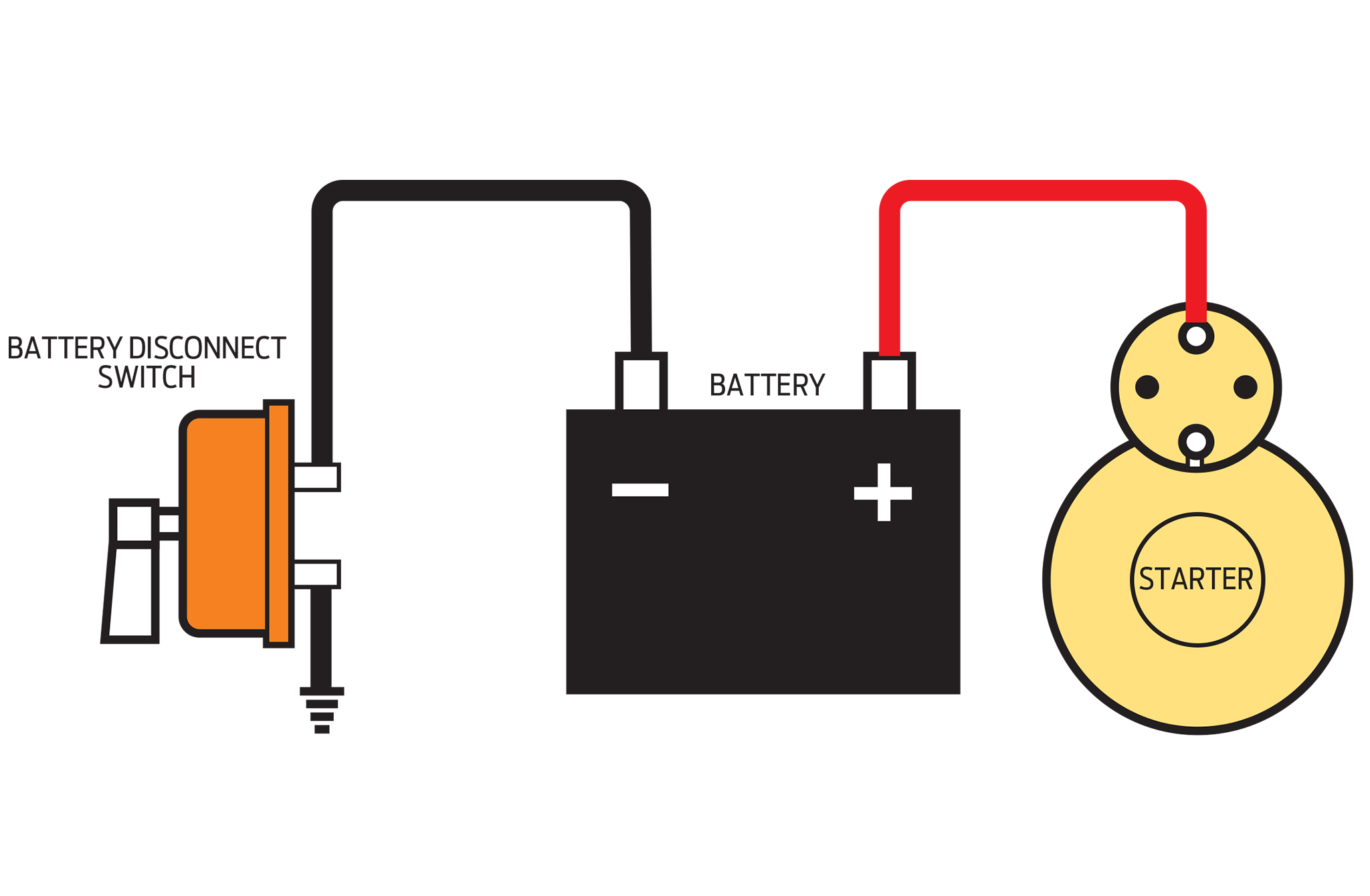
How It Works: The Circuit Explained
The basic principle is simple: the battery cutoff switch interrupts the flow of electricity from the battery to the rest of the vehicle's electrical system. The diagram shows the positive (+) battery cable running from the battery's positive terminal to one terminal of the cutoff switch. The other terminal of the cutoff switch then connects to the vehicle's electrical system via another heavy-gauge cable. When the switch is in the "on" position, the circuit is complete, and electricity can flow from the battery to power the vehicle's systems. When the switch is in the "off" position, the circuit is broken, and no electricity can flow, effectively isolating the battery. The negative (-) battery cable remains connected to the vehicle's chassis ground, providing a return path for electrical current when the cutoff switch is "on." It is crucial to install the cutoff switch on the positive side of the circuit. Installing it on the negative side might work, but it is generally considered less safe and can potentially bypass some safety features built into the electrical system.
Real-World Use and Basic Troubleshooting Tips
Let's say you've installed the cutoff switch, and something isn't working as expected. Here are a few troubleshooting tips:
- No Power at All: Double-check that the cutoff switch is in the "on" position. Verify that the connections at the battery terminals and the cutoff switch terminals are clean, tight, and free from corrosion. Use a multimeter to test the voltage at the battery terminals and at the terminals of the cutoff switch to confirm that the battery is charged and that the switch is passing current when in the "on" position.
- Intermittent Power: This could be caused by a loose connection or a faulty switch. Inspect all connections for looseness or corrosion. Try wiggling the cutoff switch to see if the power flickers. If so, the switch may need to be replaced.
- Excessive Battery Drain: If you're still experiencing battery drain even with the cutoff switch "off," there might be a wiring issue, such as a short circuit bypassing the switch. Carefully inspect the wiring around the cutoff switch and battery for any signs of damage or exposed wires.
Safety First: Handling Risky Components
Working with automotive electrical systems involves inherent risks. Always disconnect the negative battery cable before working on any electrical components, even with the cutoff switch in the "off" position, as a precaution. Batteries contain sulfuric acid, which can cause severe burns. Wear eye protection and gloves when handling batteries and battery cables. The high current that can flow through the battery cables can generate significant heat and cause fires if a short circuit occurs. Ensure that all wiring is properly insulated and routed away from sharp edges or moving parts. If you're unsure about any aspect of the installation or troubleshooting process, consult a qualified automotive electrician. A mistake with the high-current side of your car's electrical system can be disastrous.
Conclusion
Understanding the battery cutoff switch wiring diagram is a valuable skill for any car enthusiast. It empowers you to safely maintain, modify, and secure your vehicle's electrical system. By following the diagram carefully and taking necessary safety precautions, you can enjoy the benefits of a battery cutoff switch for years to come. Remember to always double-check your work and consult a professional if you're unsure about anything.
We have a detailed PDF file containing this wiring diagram that you can download. It includes more specific details and variations for different switch types. Feel free to reach out to us to get the file, and happy wrenching!