Battery Isolator Wiring Diagram Manufacturers
Understanding battery isolator wiring diagrams is crucial for anyone working on dual battery systems, whether for recreational vehicles, off-road vehicles, or even marine applications. These diagrams provide a roadmap for connecting multiple batteries while ensuring they function correctly and safely. Whether you're troubleshooting an existing system, installing a new one, or simply expanding your automotive electrical knowledge, mastering these diagrams is a valuable skill.
Purpose of a Battery Isolator Wiring Diagram
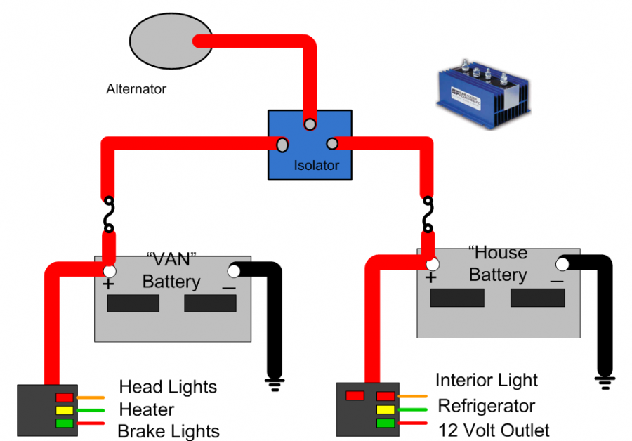
A battery isolator wiring diagram serves as a visual guide for connecting a battery isolator within a dual battery system. Its primary purpose is to illustrate how the isolator interacts with the vehicle's electrical system, the main battery (also called the starting battery), and the auxiliary battery (also called the house battery or deep-cycle battery). This is essential for:
- Installation: Guiding the correct placement and wiring of the isolator during a new system installation.
- Troubleshooting: Helping identify and diagnose issues within the battery system, such as charging problems or parasitic draws.
- Repair: Showing the proper connections for replacing faulty components, including the isolator itself, batteries, or wiring.
- Understanding: Providing a comprehensive overview of the system's operation for better maintenance and upgrades.
Without a clear diagram, attempting to wire a dual battery system can lead to incorrect connections, component damage, and even safety hazards.
Key Specs and Main Parts
Before diving into the diagram, it's important to understand the core components and their specifications:
Main Parts:
- Battery Isolator: The heart of the system. It allows the alternator to charge both batteries but prevents the auxiliary battery from draining the main battery. Common types include:
- Diode Isolators: Older technology, simple but suffer from voltage drop.
- FET (Field-Effect Transistor) Isolators: More efficient, less voltage drop.
- Solenoid Isolators (Battery Combiners/Automatic Charging Relays - ACRs): Use a relay to connect the batteries when charging voltage is detected.
- Main Battery (Starting Battery): The battery used to start the vehicle's engine. Typically a lead-acid or AGM battery.
- Auxiliary Battery (House Battery): A deep-cycle battery designed to provide power to accessories when the engine is off. Can be lead-acid, AGM, Gel, or Lithium (LiFePO4).
- Alternator: The charging source for the batteries when the engine is running.
- Fuses/Circuit Breakers: Essential for protecting the system from overcurrent and short circuits.
- Wiring: Heavy-gauge wiring is crucial for carrying the high currents involved.
- Grounding Points: Secure and clean grounding points are essential for proper circuit function.
Key Specs:
- Voltage Rating: Typically 12V or 24V, depending on the vehicle's electrical system.
- Current Rating (Amps): The maximum current the isolator can handle. This needs to be sufficient for the alternator's output and the expected load on the auxiliary battery. Higher amperage isolators are more robust.
- Battery Type Compatibility: Some isolators are designed for specific battery types (e.g., AGM, Lithium). Using the wrong type can damage the batteries.
- Voltage Drop (for Diode Isolators): The voltage loss across the isolator. This can affect charging efficiency. FET isolators minimize this.
- Activation Voltage (for ACRs): The voltage level at which the relay closes, connecting the batteries.
Symbols in a Battery Isolator Wiring Diagram
Understanding the symbols is key to interpreting the diagram. Here's a breakdown of common symbols:
- Solid Lines: Represent wires. Heavier lines usually indicate thicker gauge wires.
- Dashed Lines: Can represent optional connections, signal wires, or ground connections.
- Colors: Wires are often color-coded (e.g., red for positive, black for negative/ground). Adhering to these color codes during installation is highly recommended.
- Battery Symbol: A rectangle with "+" and "-" signs indicating the positive and negative terminals.
- Alternator Symbol: Varies, often a circle with internal symbols representing the stator windings.
- Fuse/Circuit Breaker Symbol: A squiggly line within a rectangle.
- Ground Symbol: Three descending horizontal lines, indicating a connection to the vehicle's chassis or a dedicated ground point.
- Isolator Symbol: Varies depending on the type (diode, FET, relay). Diode isolators are often represented by a diode symbol (triangle pointing to a line). Relay-based isolators will show a relay coil and switch contacts.
- Connection Dot: A small dot where wires connect. If there is no dot, the wires are considered to be crossing without connecting.
How It Works
The basic principle of a battery isolator is to allow the alternator to charge both the main and auxiliary batteries while preventing the auxiliary battery from discharging into the main battery when the engine is off. Here's a general overview of how a typical system works:
- Engine Running (Charging): When the engine is running, the alternator produces voltage. This voltage is sensed by the isolator.
- Isolator Activation:
- Diode Isolator: Always allows current to flow in one direction (from alternator to batteries). However, a small voltage drop will occur.
- FET Isolator: Allows current to flow with minimal voltage drop.
- ACR: Senses the alternator voltage and closes a relay, connecting the main and auxiliary batteries in parallel. This allows the alternator to charge both batteries simultaneously.
- Battery Charging: Both the main and auxiliary batteries receive charging current from the alternator.
- Engine Off (No Charging): When the engine is off, the alternator stops producing voltage.
- Isolation: The isolator prevents the auxiliary battery from backfeeding into the main battery. This ensures the main battery retains its charge for starting the vehicle. The load connected to the aux battery will draw power only from aux battery.
A well-designed system should prioritize charging the main battery first and then divert the remaining current to the auxiliary battery. More advanced isolators and battery management systems can also incorporate temperature compensation and other features to optimize charging and extend battery life.
Real-World Use & Basic Troubleshooting Tips
Here are some common scenarios and troubleshooting tips:
- Auxiliary Battery Not Charging:
- Check the isolator's connections and fuse.
- Verify the isolator is receiving power from the alternator.
- Test the isolator's functionality with a multimeter. For ACRs, check if the relay is clicking when the engine is started.
- Consider voltage drop if using a diode isolator. You may need to adjust the alternator's voltage regulator.
- Main Battery Draining When Engine Is Off:
- The isolator may be faulty and allowing backfeeding. Test the isolator.
- A parasitic draw on the main battery might exist, unrelated to the auxiliary system.
- Blown Fuses:
- Indicates an overcurrent situation or a short circuit. Identify the source of the short before replacing the fuse.
- Ensure the fuses are properly sized for the circuit.
- Low Voltage Readings:
- Check for corroded or loose connections.
- Ensure the batteries are in good condition and properly charged.
- Consider voltage drop across long cable runs. Use thicker gauge wire.
Safety Considerations
Working with automotive electrical systems involves inherent risks. Always disconnect the negative terminal of the main battery before working on the system.
- High Current: Batteries can deliver very high currents, which can cause severe burns or even death. Use insulated tools and avoid short circuits.
- Battery Acid: Lead-acid batteries contain sulfuric acid, which is corrosive. Wear eye protection and gloves.
- Explosive Gases: Batteries can produce hydrogen gas, which is flammable and explosive. Ensure good ventilation when working around batteries.
- Component Ratings: Ensure all components (isolator, fuses, wiring) are rated for the appropriate voltage and current. Undersized components can overheat and fail, potentially causing a fire.
This article provides a solid foundation for understanding battery isolator wiring diagrams. It empowers you to confidently tackle dual battery system installations, repairs, and troubleshooting. A correct wiring diagram is crucial. We have compiled a basic battery isolator wiring diagram and related resources for further exploration which you can download via this link [Link to Downloadable Diagram]. Remember to always prioritize safety and consult with a qualified professional if you're unsure about any aspect of the work.