Bee R Rev Limiter Wiring Diagram
This article provides a detailed explanation of the Bee*R Rev Limiter wiring diagram, empowering you to understand its function, wiring, and troubleshooting. Whether you're diagnosing issues, performing a fresh install, or simply deepening your knowledge of aftermarket engine management systems, this guide offers a comprehensive overview. We assume you possess a foundational understanding of automotive electrical systems, including how to use a multimeter and read basic wiring diagrams.
Purpose of Understanding the Bee*R Rev Limiter Wiring Diagram
The Bee*R Rev Limiter is an aftermarket device designed to add a secondary, often aggressive, rev limit to a vehicle's engine. This functionality is primarily for aesthetic purposes (producing flames and loud exhaust pops, often referred to as "anti-lag" for some applications). Understanding the wiring diagram is crucial for several reasons:
- Installation: Correct wiring is paramount for proper function and to avoid damaging the device or your vehicle's ECU (Engine Control Unit).
- Troubleshooting: When the rev limiter malfunctions (e.g., doesn't activate, activates at the wrong RPM, causes engine misfires), the wiring diagram is your primary tool for diagnosing the problem.
- Modification and Repair: You might need to modify the wiring to suit your specific vehicle or repair damaged wiring connections.
- Learning: Studying the wiring diagram enhances your understanding of how aftermarket electronics interface with your car's engine management system.
Key Specs and Main Parts of the Bee*R Rev Limiter
Before diving into the wiring diagram, let's review the key specifications and main components:
- Input Voltage: Typically 12V DC. Confirm the specific voltage range on your unit. Operating outside this range can damage the device.
- RPM Range: Usually adjustable via rotary dials, covering a wide RPM spectrum from idle to beyond the factory rev limit.
- Rev Limit Type: Most Bee*R units function by interrupting the ignition signal to specific cylinders.
- Main Components:
- Control Unit: The main processing unit that houses the electronics and adjustment dials.
- Wiring Harness: Contains the necessary wires for connecting to the vehicle's electrical system.
- RPM Signal Input: Receives the RPM signal from the ignition coil or ECU.
- Ground Wire: Provides a common ground reference.
- Power Wire: Connects to a 12V power source, usually ignition-switched.
- Ignition Cut Wires: These wires interrupt the ignition signal to specific cylinders (number varies depending on unit).
- Activation Wire (Optional): A wire that, when grounded, activates the rev limiter. Some units use a switch or button connected to this wire.
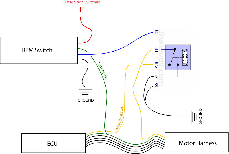
Symbols and Conventions in the Wiring Diagram
Understanding the symbols used in the wiring diagram is fundamental. Here's a breakdown of common symbols:
- Solid Lines: Represent wires. Thicker lines often indicate wires with higher current capacity.
- Dashed Lines: May represent shielding or less critical connections.
- Colors: Wires are typically color-coded (e.g., Red for power, Black for ground). Always confirm the wire color on *your* specific unit, as they can vary.
- Circles: Often indicate connectors or splices.
- Ground Symbol (⏚): Indicates a connection to the vehicle's chassis ground.
- Battery Symbol: Represents the 12V battery.
- Fuse Symbol: Shows the location of a fuse in the circuit, essential for protection.
- Resistor Symbol (Ω): Represents a resistor, used to limit current or provide voltage division.
- Capacitor Symbol (||): Represents a capacitor, used for filtering or energy storage.
- Transistor Symbol: Represents a transistor, a semiconductor device used for switching or amplification (common in the Bee*R's ignition cut circuitry).
- ECU Symbol: A rectangle or box representing the Engine Control Unit.
- Ignition Coil Symbol: Represents the ignition coil.
The diagram will also show how wires are connected (e.g., T-taps, butt connectors, soldering). Understanding these connection methods is crucial for proper installation and repair.
How the Bee*R Rev Limiter Works (Electronically)
The Bee*R Rev Limiter functions by monitoring the engine's RPM signal. This signal is typically derived from the ignition coil's negative terminal or, in newer vehicles, directly from the ECU. The control unit then compares the incoming RPM signal to the user-defined rev limit settings.
When the engine RPM reaches the preset limit, the Bee*R unit interrupts the ignition signal to one or more cylinders. This interruption prevents combustion in those cylinders, causing a misfire and a rapid drop in engine speed. The rapid cycling between firing and misfiring creates the characteristic "popping" and "banging" sound, and potentially flames from the exhaust. The aggression of the effect is often controlled by the number of cylinders cut and the frequency of the cut. More aggressive settings (cutting multiple cylinders rapidly) are more likely to damage exhaust components. The dials on the unit control the activation RPM, and how aggressively it cuts the engine.
Some Bee*R units include a secondary rev limit that's activated when a specific condition is met, like grounding a dedicated activation wire. This allows for on-demand activation of the rev limiter effect.
Real-World Use: Basic Troubleshooting Tips
Here are some common issues and troubleshooting steps:
- No Activation:
- Verify power and ground connections to the Bee*R unit. Use a multimeter to confirm 12V at the power wire and continuity to ground at the ground wire.
- Check the RPM signal input wire. Is it properly connected to the ignition coil or ECU? Use a multimeter (set to AC voltage) to see if a signal is present when the engine is running.
- Ensure the activation wire (if present) is properly connected to a switch or ground.
- Inspect the fuse for the Bee*R unit.
- Erratic Activation or Misfires at Low RPM:
- Double-check the RPM signal input. A noisy or weak signal can cause erratic activation. Consider using a shielded wire for the RPM signal to minimize interference.
- Verify that the RPM settings on the control unit are correctly configured.
- Inspect the ignition cut wires for any shorts or loose connections.
- Engine Warning Lights:
- Cutting ignition can trigger check engine lights related to misfires. An OBDII scanner can confirm these codes. While usually harmless, persistent misfires can damage the catalytic converter over time.
Safety Considerations
Working with automotive electrical systems can be dangerous. Always disconnect the battery's negative terminal before working on any wiring. Never work on the wiring while the engine is running.
- ECU Damage: Incorrect wiring can damage your vehicle's ECU, potentially leading to costly repairs. Double-check all connections before powering on the unit.
- Ignition Coil Damage: Some installations require tapping into or cutting the ignition coil wiring. Improper installation can damage the ignition coil.
- Exhaust System Damage: Aggressive rev limiter settings can cause excessive heat and pressure in the exhaust system, potentially damaging catalytic converters and other components. Use caution when adjusting the rev limiter settings.
- Electrical Shock: Although the voltage levels are typically low, avoid touching bare wires or connectors while the system is powered on.
Important Note: This information is for educational purposes only. Consult with a qualified mechanic before installing or modifying any aftermarket electronics on your vehicle.
For a detailed Bee*R Rev Limiter wiring diagram specific to your vehicle and unit, remember to consult the manufacturer's instructions. We have a standard wiring diagram file available for download; please contact us with your specific model for the document.