
Best Automotive Wiring Diagram Software
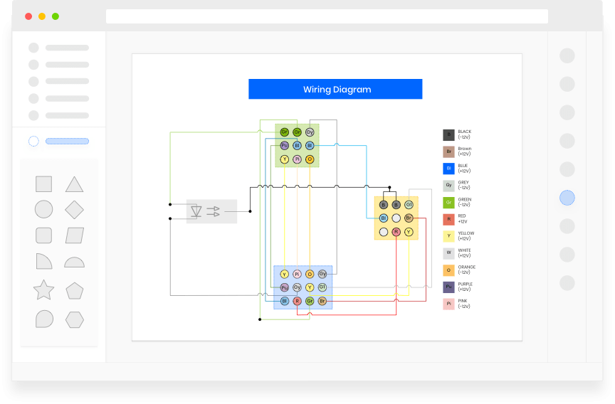
Alright, let's talk about automotive wiring diagrams. Whether you're chasing down a gremlin in your turn signals, adding aftermarket accessories, or just trying to understand how your car's electrical system actually works, a good wiring diagram is your absolute best friend. Forget blindly poking around with a multimeter; a wiring diagram is the roadmap that guides you through the labyrinth of wires and components.
Purpose of Automotive Wiring Diagrams
Why are these diagrams so crucial? Think of it this way: your car's electrical system is its nervous system. A wiring diagram is like the detailed anatomical chart for that system. Its primary purpose is to provide a visual representation of all the electrical circuits, components, and their interconnections within a vehicle. Without it, you're essentially troubleshooting with your eyes closed.
Here's a breakdown of the common uses:
- Troubleshooting: Diagnosing electrical faults, like shorts, opens, or voltage drops. Knowing where a wire goes allows you to pinpoint the problem quickly.
- Repairing: Fixing damaged wiring, replacing components, or re-establishing connections after corrosion.
- Modification: Installing aftermarket accessories such as stereos, alarms, lights, and performance upgrades. This helps you tap into the correct circuits and avoid damaging existing systems.
- Learning: Understanding how different systems within the vehicle function and interact with each other. Want to know how the ABS works? The wiring diagram is a great place to start.
- Restoration: Restoring classic cars where original wiring has deteriorated or been improperly modified.
Key Specs and Main Parts of a Wiring Diagram
A wiring diagram isn't just a random collection of lines. It's organized and standardized. Here's what you'll typically find:
- Power Source: This usually represents the battery (12V DC in most cars) and ground connection. It's the origin of the electrical energy.
- Components: These are the actual electrical parts: lights, sensors, actuators, relays, switches, fuses, resistors, and the ECU (Engine Control Unit). Each component will have a specific symbol.
- Wiring Harness: This is the bundle of wires that connects everything. Diagrams often show the harness routing for easier identification in the vehicle.
- Connectors: Where wires join together or connect to components. These are indicated by specific symbols, and often include a pin number or code.
- Ground Points: Locations where components are electrically connected to the vehicle's chassis, providing a return path for the current.
- Fuses and Circuit Breakers: Overcurrent protection devices that interrupt the circuit if there is a fault. Their location and amperage rating are usually specified.
Think of the wiring harness as the highway system, and the connectors as the on-ramps and off-ramps. Each component is a destination along that highway.
Understanding Wiring Diagram Symbols
Navigating a wiring diagram is like learning a new language. Here's a primer on the key symbols you'll encounter:
Lines:
- Solid Lines: Represent wires carrying electrical current. The thickness of the line usually doesn't indicate wire gauge, but it might in some diagrams.
- Dashed Lines: Indicate shielded wires or wires that are part of a data bus network (like CAN bus).
- Arrows: Show the direction of current flow in a circuit.
Colors:
Wire colors are extremely important. They allow you to identify specific wires within a harness. Most diagrams use abbreviations for colors (e.g., "BK" for black, "RD" for red, "BL" for blue, "GN" for green, "WT" for white, "YE" for yellow). A wire might be labeled "RD/BK" indicating a red wire with a black stripe.
Icons:
Component symbols vary, but common ones include:
- Resistor: A zig-zag line.
- Capacitor: Two parallel lines.
- Diode: A triangle pointing to a vertical line.
- Relay: A coil representing the electromagnet, and a switch showing the contacts.
- Switch: A line that opens or closes to complete or interrupt a circuit.
- Ground: Often depicted as a series of horizontal lines decreasing in size, resembling an upside-down Christmas tree.
- Fuse: A line with an "S" shape in the middle.
- Battery: A series of alternating long and short parallel lines.
Remember to always refer to the diagram's legend or key for a complete explanation of all symbols used.
How It Works: Following the Circuit
The basic principle is tracing the flow of electricity from the power source (battery) through the circuit components and back to ground. Here's a simplified example:
- Power Source: The battery provides 12V.
- Fuse: The current flows through a fuse, protecting the circuit from overloads.
- Switch: The switch is in the "off" position, interrupting the circuit.
- Turn Switch "On": Closing the switch completes the circuit.
- Component: The current now flows to a light bulb (the component).
- Ground: The current flows through the light bulb, causing it to illuminate, and then returns to the battery's negative terminal (ground).
By carefully following the lines, symbols, and color codes, you can trace the path of electricity and identify any breaks or shorts in the circuit.
Real-World Use: Basic Troubleshooting Tips
Let's say your headlights aren't working. Here's how a wiring diagram can help:
- Consult the Diagram: Find the wiring diagram for the headlight circuit.
- Identify Key Components: Locate the headlights, switch, relay (if present), fuse, and ground connections.
- Check the Fuse: Use a multimeter to test the fuse for continuity. If it's blown, replace it with the correct amperage rating.
- Test the Switch: Use a multimeter to check if the switch is providing power to the headlight relay (if applicable) when turned on.
- Check the Relay: If a relay is involved, test it to ensure it's functioning properly.
- Check the Headlights: Test the headlights directly by applying 12V to them. If they don't light up, they are likely faulty.
- Check Ground Connections: Ensure the ground connections are clean and secure. A bad ground can cause all sorts of electrical problems.
- Voltage Drop Test: Perform a voltage drop test along the circuit to identify any points of excessive resistance. A high voltage drop indicates a poor connection or damaged wire.
Remember to always start with the simplest checks (like the fuse) before moving on to more complex testing.
Safety Considerations
Working with automotive electrical systems can be dangerous. Here are some crucial safety precautions:
- Disconnect the Battery: Always disconnect the negative terminal of the battery before working on any electrical components. This prevents accidental shorts and shocks.
- Identify Risky Components: Be extra cautious around components like the airbag system, ABS system, and ECU. Improper handling can cause serious injury or damage. It is recommended to let the professionals deal with airbag and ABS system.
- Use Proper Tools: Use insulated tools specifically designed for automotive electrical work.
- Avoid Working in Wet Conditions: Water conducts electricity, increasing the risk of electric shock.
- Double-Check Your Work: Before reconnecting the battery, carefully review your work to ensure all connections are secure and wires are properly routed.
High-current circuits, like those for the starter motor or alternator, can deliver a significant shock. Treat them with extreme respect.
With a good wiring diagram and a methodical approach, you can confidently tackle most automotive electrical repairs and modifications. Remember safety first, and don't be afraid to consult with a professional if you're unsure about anything.
We have the wiring diagram file mentioned in this article. Contact us to download the diagram!