Blower Motor Resistor Wiring Diagram
Understanding the blower motor resistor wiring diagram is crucial for anyone tackling automotive HVAC (Heating, Ventilation, and Air Conditioning) repairs or modifications. This diagram serves as a roadmap to diagnose issues with your vehicle's fan speed control, potentially saving you money and time compared to taking it to a professional mechanic. Whether you're troubleshooting a malfunctioning fan, upgrading your climate control system, or simply learning more about your car's electrical system, mastering this diagram is a valuable skill.
Purpose of a Blower Motor Resistor Wiring Diagram
The primary purpose of a blower motor resistor wiring diagram is to illustrate the electrical connections within the blower motor control circuit. This circuit allows you to select different fan speeds. The diagram shows how the blower motor resistor, blower motor, switch, fuse, and other components are interconnected. This visual representation is invaluable for:
- Diagnosis: Identifying faulty components within the blower motor circuit.
- Repair: Replacing or repairing damaged wiring or components accurately.
- Modification: Implementing upgrades to your HVAC system, such as installing a new blower motor or fan speed controller.
- Understanding: Gaining a deeper understanding of your vehicle's electrical system.
Key Specifications and Main Parts
Before diving into the diagram itself, let's identify the key components and their specifications:
Main Parts
- Blower Motor: The electric motor that drives the fan, circulating air through the HVAC system. It typically requires 12V DC power.
- Blower Motor Resistor (or Resistor Block): A series of resistors used to control the voltage supplied to the blower motor, thereby controlling fan speed. Each resistor corresponds to a different speed setting.
- Blower Motor Switch (Fan Speed Switch): A multi-position switch that selects which resistor (or direct connection) is used, determining the fan speed.
- Fuse: A safety device that protects the circuit from overcurrents. Blower motor circuits typically use a relatively high-amperage fuse (e.g., 20A, 30A) due to the motor's power consumption.
- Relay (Optional): Some vehicles utilize a relay to switch power to the blower motor, especially in systems with higher amperage draw. This relay is controlled by the fan speed switch.
- Wiring Harness: The collection of wires connecting all components. Wire gauge (thickness) is important; thinner wires can overheat if carrying too much current.
Key Specs
- Voltage: Typically 12V DC in passenger vehicles.
- Resistance Values: Each resistor in the blower motor resistor block has a different resistance value (measured in ohms, Ω). Higher resistance results in lower voltage to the motor and a slower fan speed.
- Fuse Rating: Expressed in Amperes (A). Select the correct fuse rating to prevent nuisance trips while still providing adequate protection.
- Wire Gauge: Expressed in AWG (American Wire Gauge). Lower AWG numbers indicate thicker wires with higher current-carrying capacity.
Understanding the Symbols
Electrical wiring diagrams use standard symbols to represent components and connections. Here's a breakdown of common symbols you'll encounter in a blower motor resistor wiring diagram:
- Solid Lines: Represent wires. Thicker lines may indicate wires with larger gauge.
- Dashed Lines: May represent shielded cables or connections that are optional or only present in certain configurations.
- Colors: Each wire is typically color-coded. Common colors include red (power), black (ground), and various other colors for signal or control wires. The color code is usually listed on the diagram.
- Resistor: A jagged line represents a resistor.
- Switch: A lever or series of levers connected to contact points represents a switch. The diagram shows the switch's different positions and the corresponding connections.
- Motor: A circle with an "M" inside represents a motor.
- Fuse: A line crossing a squiggly line or a small box with a number inside represents a fuse. The number indicates the fuse's amperage rating.
- Ground: A symbol resembling an upside-down triangle or a series of horizontal lines decreasing in size represents a ground connection.
- Relay: A rectangle containing a coil symbol and a switch symbol represents a relay.
- Splices/Connections: A dot where two or more lines intersect indicates a connection. If lines cross without a dot, it indicates that the wires are not connected.
Important: Always refer to the specific wiring diagram for your vehicle make, model, and year, as symbols and conventions can vary slightly.
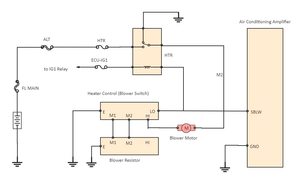
How It Works: The Blower Motor Resistor Circuit
The blower motor circuit is a relatively simple circuit that controls the speed of the blower motor. Power flows from the battery, through a fuse, and then to the blower motor switch. The blower motor switch allows the user to select different fan speeds. When a low speed is selected, the current flows through a high-resistance resistor, reducing the voltage to the blower motor and causing it to spin slowly. When a high speed is selected, the current may bypass the resistors entirely, allowing full voltage to reach the blower motor and causing it to spin at its maximum speed. The blower motor is connected to ground, completing the circuit.
Here's a more detailed breakdown:
- Power Supply: The circuit receives power from the vehicle's battery through a fuse.
- Switch Selection: When you turn the fan speed switch, you're selecting a specific path for the current to flow.
- Resistor Network: Each position on the switch directs current through a different resistor within the resistor block. Higher resistance means lower voltage to the motor, resulting in lower speed.
- Blower Motor Operation: The voltage applied to the blower motor determines its speed.
- Ground Connection: The motor is connected to the vehicle's chassis ground, completing the circuit.
Real-World Use: Troubleshooting Tips
Here are some common blower motor resistor problems and how the wiring diagram can help you troubleshoot them:
- No Fan Operation at All: Check the fuse first! If the fuse is blown, replace it with one of the correct amperage. If the fuse blows immediately upon replacement, there's a short circuit. Use the wiring diagram to trace the circuit and identify the short. Also, check the blower motor relay (if equipped).
- Only Works on High Speed: This is a classic symptom of a failed blower motor resistor. Usually, only the resistor for the low speeds burn out, meaning high speed, which often bypasses the resistor block entirely, will still work. The wiring diagram will show you which resistor corresponds to which speed.
- Fan Operates on Some Speeds but Not Others: This indicates a problem with a specific resistor or the wiring to that resistor. Use a multimeter to test the resistance values of the individual resistors. Compare the readings to the expected values (if available) or to the readings of a known good resistor block.
- Intermittent Operation: Loose connections or corroded terminals can cause intermittent fan operation. The wiring diagram helps you identify all connection points to inspect.
Tip: A multimeter is an indispensable tool for troubleshooting electrical circuits. Learn how to use it to measure voltage, resistance, and continuity.
Safety Precautions
Working with electrical circuits can be dangerous. Always take the following precautions:
- Disconnect the Battery: Before working on any electrical component, disconnect the negative terminal of the battery to prevent accidental shocks.
- Handle Resistors with Care: Blower motor resistors can get very hot during operation. Allow them to cool down before handling them. A failed resistor can also be a fire hazard.
- Avoid Shorts: Be careful not to create short circuits while working on the wiring. A short circuit can damage components and potentially start a fire.
- Use Appropriate Tools: Use insulated tools designed for electrical work.
- Double-Check Your Work: After making any repairs or modifications, double-check your wiring connections before reconnecting the battery.
Warning: Blower motor resistors can get extremely hot and can cause burns. Ensure the system is cool before working on it. Always prioritize safety when working on your vehicle's electrical system.
We have a comprehensive blower motor resistor wiring diagram available for download to further assist you in your repairs and modifications. Understanding and utilizing this diagram will empower you to confidently diagnose and resolve blower motor issues, saving you time and money while expanding your automotive knowledge.