Blower Motor Resistor Wiring Harness
Alright, let's dive into the often-overlooked but crucial part of your car's HVAC system: the blower motor resistor wiring harness. Understanding this system is essential if you're tackling climate control issues, diagnosing electrical problems, or even just curious about how your car keeps you comfortable. This article will equip you with the knowledge to confidently approach repairs, modifications, and general troubleshooting.
Purpose and Importance
Why should you care about the blower motor resistor wiring harness? Simple: your car's climate control system relies on it. The blower motor itself is responsible for circulating air through your vents – whether it's hot air from the heater core or cold air from the evaporator. The resistor and its wiring harness are the control center for the blower's speed. Without them functioning correctly, you might find yourself stuck with only one fan speed (usually high), or worse, no fan at all. This understanding is critical for DIY repairs, upgrading components, or even just understanding a diagnostic trouble code (DTC) pointing to HVAC issues.
Key Specs and Main Parts
Let's break down the components you'll typically find in a blower motor resistor wiring harness system:
- Blower Motor Resistor: This is the heart of the system. It’s a set of resistors, typically wire-wound or ceramic-based, designed to drop voltage to the blower motor, controlling its speed. Each resistor corresponds to a different fan speed setting. A lower resistance allows more current and thus a higher fan speed.
- Blower Motor: An electric motor that spins the fan, forcing air through the HVAC system. It's powered by the electrical system, with its speed controlled by the resistor.
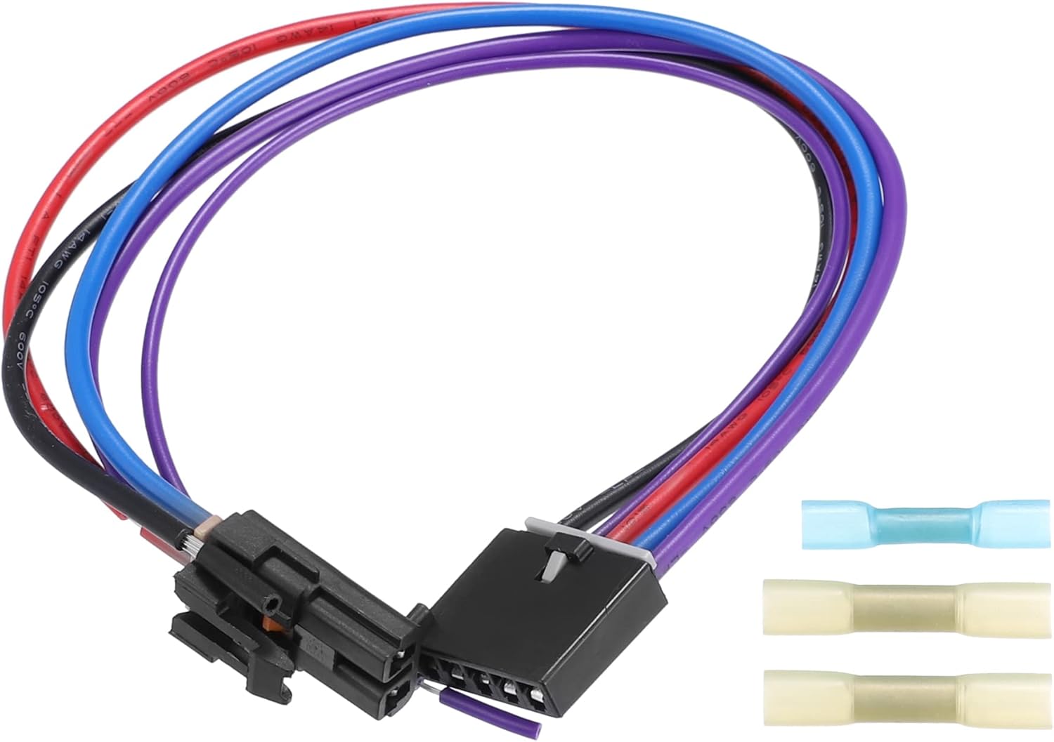
- Wiring Harness: This is the collection of wires that connect the resistor, blower motor, mode switch (or HVAC control panel), and the vehicle's power source (typically the battery or a fuse box). It's usually a multi-pin connector plugged into the resistor.
- Mode Switch (HVAC Control Panel): Located inside of the vehicle's cabin; allows the user to dictate the position of the louvers inside of the HVAC system. It controls which resistor is active. In modern vehicles, this may be a fully electronic control module.
- Fuses and Relays: These protect the circuit from overloads and control the high current draw of the blower motor.
Common Specifications: You'll often see the resistor pack rated in terms of resistance values for each speed setting (e.g., 0.5 ohms for low, 0.2 ohms for medium, etc.). The blower motor itself will have a voltage rating (typically 12V or 24V in automotive applications) and a current draw specification. Understanding these specs is crucial when replacing components.
Understanding the Wiring Diagram Symbols
Interpreting a wiring diagram is key to troubleshooting. Here's a quick rundown of common symbols:
- Solid Lines: Represent wires. Thicker lines usually indicate wires carrying higher current.
- Dashed Lines: May indicate shielded wires or communication lines (like those in a CAN bus system, though this is less common in purely analog blower motor systems).
- Circles with Numbers: Represent connector pins. These numbers are crucial for identifying which wire goes where in a multi-pin connector.
- Resistor Symbol (Zig-zag line): Indicates a resistor. In the blower motor resistor circuit, you'll see multiple resistors connected in a specific arrangement.
- Motor Symbol (Circle with an "M"): Represents the blower motor itself.
- Ground Symbol (Series of decreasing horizontal lines or an inverted triangle): Indicates a connection to the vehicle's chassis ground.
- Fuse Symbol (Line with a loop or a rectangle with an "F"): Represents a fuse.
- Relay Symbol (Coil and switch contacts): Shows the relay coil and the contacts it controls.
Wire Colors: Wire colors are extremely important. They provide a standardized way to identify wires throughout the vehicle. Common colors include Red (power), Black (ground), and various other colors for signal and control wires. Never assume a wire's function based on its location alone; always verify with the wiring diagram.
How It Works
The blower motor circuit is relatively straightforward. Power from the battery (protected by a fuse) is fed to the mode switch (or HVAC control panel). When you select a fan speed, the switch directs power through a specific resistor in the resistor pack. This resistor drops the voltage, reducing the current flowing to the blower motor. The lower the resistance, the higher the current and the faster the fan spins. Finally, the current returns to the system through the ground wire. In systems with a blower motor relay, the mode switch activates the relay, which then provides power to the resistor pack and blower motor.
Key Concept: The resistor pack is essentially a voltage divider. Each resistor creates a different voltage drop, resulting in different fan speeds.
Real-World Use: Basic Troubleshooting
Here are some common problems and troubleshooting tips:
- No Fan at Any Speed: Check the fuse first. Then, check the blower motor relay (if equipped). If those are good, suspect the blower motor itself or a break in the main power or ground wires.
- Fan Works Only on High: This is a classic symptom of a failed blower motor resistor. Usually, one or more of the resistors have burned out, leaving only the direct (un-resisted) connection for high speed.
- Intermittent Fan Operation: This could be a loose connection in the wiring harness, a failing relay, or a worn-out blower motor. Inspect the connector at the resistor for corrosion or damage.
- Burning Smell: A burning smell often indicates overheating in the resistor pack or blower motor. This could be caused by a restricted airflow (dirty cabin air filter), a failing blower motor, or a short circuit.
Troubleshooting Steps:
- Visual Inspection: Check the wiring harness for damaged wires, melted connectors, or corrosion. Look for signs of overheating around the resistor pack.
- Voltage Testing: Use a multimeter to check for voltage at the blower motor and resistor pack. Verify that you're getting power to the system and that the resistors are dropping the voltage as expected.
- Continuity Testing: Use a multimeter to check for continuity in the wiring harness. This helps identify broken wires or bad connections.
- Resistance Testing: Measure the resistance of each resistor in the resistor pack. Compare your readings to the specifications for your vehicle.
Safety Considerations
Working on automotive electrical systems can be dangerous. Here are some key safety precautions:
- Disconnect the Battery: Always disconnect the negative battery cable before working on any electrical components. This prevents accidental shorts and electrical shocks.
- Be Aware of Hot Components: The blower motor resistor can get very hot during operation. Allow it to cool down before handling it.
- Use Proper Tools: Use insulated tools designed for automotive electrical work.
- Don't Guess: Always refer to the wiring diagram for your specific vehicle. Don't make assumptions about wire functions or connections.
- High Current components The Blower motor is a high current device and requires a large guage wire to supply power to it. Faulty wiring can result in a fire hazard. Always use the proper size wire and connectors when repairing or replacing components in the blower motor circuit.
Diagram Download
Understanding the intricacies of the blower motor resistor wiring harness is critical for effective troubleshooting and repairs. To help you further, we have a detailed wiring diagram available for download. This diagram includes wire colors, connector pinouts, and component locations. Having this resource at your fingertips will significantly simplify your diagnostic process. Contact us to request access to the download file.
With this knowledge and the right resources, you'll be well-equipped to tackle any blower motor resistor wiring harness issues that come your way. Good luck!