
Blueprint Ford 4.6 Engine Parts Diagram
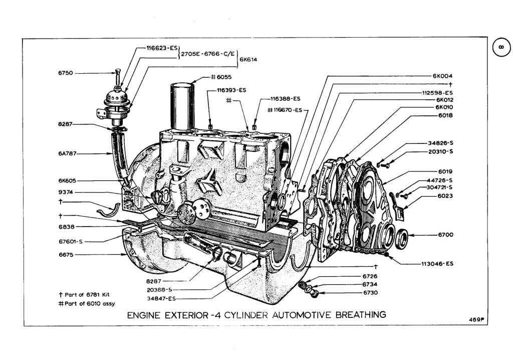
Alright, let's dive into the blueprint of the Ford 4.6L engine. Think of this article, and the diagram you can download, as your detailed roadmap for understanding, troubleshooting, and even modifying this incredibly popular V8. We're talking about an engine that powered everything from Mustangs to Crown Victorias, making it a staple for a reason. This guide is for the DIY mechanic who’s looking to go beyond basic maintenance and really understand what's under the hood.
Purpose of a 4.6L Engine Diagram
Why bother with a detailed engine parts diagram? Simple: it's invaluable for:
- Repair Work: Quickly identifying parts, their location, and how they connect saves time and prevents costly mistakes. Imagine trying to replace a coolant temperature sensor without knowing exactly where it lives – a diagram eliminates the guesswork.
- Troubleshooting: Understanding the engine's layout and component relationships is crucial for diagnosing problems. Knowing where the MAF sensor is in relation to the throttle body, for example, can help you pinpoint intake issues.
- Modification and Upgrades: Planning performance upgrades requires a thorough understanding of the engine's architecture. Deciding whether to supercharge, turbocharge, or simply swap out camshafts becomes much more informed with a clear visual reference.
- General Learning: Even if you're not actively working on the engine, studying the diagram helps you grasp the fundamentals of internal combustion and how all the parts work together.
Key Specs and Main Parts of the 4.6L Engine
The Ford 4.6L engine, a member of the Modular engine family, came in several variations. Let's look at some common specs and the key components you'll find in the diagram:
- Displacement: 4.6 Liters (281 cubic inches).
- Configuration: V8 (eight cylinders arranged in a "V" formation).
- Valvetrain: Overhead Cam (OHC) – typically Single Overhead Cam (SOHC) or Dual Overhead Cam (DOHC), affecting the number of camshafts per cylinder head.
- Fuel Delivery: Sequential Fuel Injection (SFI).
- Firing Order: Commonly 1-3-7-2-6-5-4-8 (though variations exist).
Here are the main components you'll find detailed in the diagram, and why they're important:
- Cylinder Block: The engine's foundation, housing the cylinders and crankshaft. Usually made of cast iron or aluminum.
- Cylinder Heads: Sit atop the cylinder block, containing the valves, camshafts (if applicable), and combustion chambers.
- Crankshaft: Converts the linear motion of the pistons into rotational motion, providing power to the transmission.
- Pistons and Connecting Rods: The pistons move up and down within the cylinders, driven by combustion. Connecting rods link the pistons to the crankshaft.
- Camshaft(s): Controls the opening and closing of the intake and exhaust valves. The camshaft lobe profile dictates valve timing and lift.
- Valves (Intake and Exhaust): Regulate the flow of air and fuel into the combustion chamber and exhaust gases out.
- Intake Manifold: Distributes air to the cylinders.
- Exhaust Manifold/Headers: Collects exhaust gases from the cylinders.
- Throttle Body: Controls the amount of air entering the engine, regulated by the accelerator pedal.
- Fuel Injectors: Spray fuel into the intake ports or directly into the combustion chamber (depending on the model).
- Water Pump: Circulates coolant through the engine to regulate temperature.
- Oil Pump: Circulates oil to lubricate engine components.
- Distributor/Ignition Coils: Depending on the year and model, the 4.6L uses a distributor (older models) or individual ignition coils (COP - Coil-On-Plug) for each cylinder.
- Sensors: Critical for engine management, including the MAF (Mass Airflow) sensor, MAP (Manifold Absolute Pressure) sensor, TPS (Throttle Position Sensor), CKP (Crankshaft Position) sensor, and CMP (Camshaft Position) sensor.
Understanding the Symbols and Conventions
Engine diagrams use a standardized set of symbols and conventions to represent parts and their connections. Here's a breakdown of what to look for:
- Solid Lines: Typically represent physical connections, such as hoses, pipes, or electrical wiring. Thicker lines usually indicate main lines, while thinner lines represent smaller connections.
- Dashed Lines: Often indicate vacuum lines or control lines.
- Arrows: Show the direction of flow for fluids (coolant, oil, fuel) or electrical signals.
- Color Coding: Colors can vary depending on the diagram, but they often represent different systems. For example, blue might indicate coolant lines, red for fuel lines, and yellow for electrical wiring. Pay attention to the legend or key provided with the diagram.
- Abbreviations: Engine diagrams use abbreviations extensively. Common ones include:
- MAF: Mass Airflow sensor
- MAP: Manifold Absolute Pressure sensor
- TPS: Throttle Position Sensor
- CKP: Crankshaft Position sensor
- CMP: Camshaft Position sensor
- ECT: Engine Coolant Temperature sensor
- IAC: Idle Air Control valve
- Cutaway Views: Some diagrams use cutaway views to show the internal workings of a component, such as a fuel injector or oil pump.
How It Works (Simplified)
The 4.6L engine operates on the four-stroke combustion cycle: Intake, Compression, Combustion (Power), and Exhaust. Understanding this cycle is essential for interpreting the diagram:
- Intake: The piston moves down, drawing air and fuel (or just air in direct injection engines) into the cylinder through the open intake valve.
- Compression: The piston moves up, compressing the air-fuel mixture. Both intake and exhaust valves are closed.
- Combustion (Power): The spark plug ignites the compressed mixture, creating a powerful explosion that forces the piston down. This is the power stroke.
- Exhaust: The piston moves up, pushing the exhaust gases out of the cylinder through the open exhaust valve.
The engine diagram visually represents how all these components work together to achieve this cycle. For example, you can trace the flow of air from the air filter through the intake manifold, into the cylinders via the intake valves, and then out through the exhaust valves and exhaust system. Similarly, you can trace the fuel system, from the fuel tank to the fuel injectors.
Real-World Use: Basic Troubleshooting Tips
Here are some examples of how to use the diagram for basic troubleshooting:
- Rough Idle: If you suspect a vacuum leak, use the diagram to trace all the vacuum lines. Carefully inspect them for cracks, leaks, or loose connections. Common culprits include the PCV valve hose and the vacuum lines to the brake booster.
- Check Engine Light (CEL) - MAF Sensor Code: The diagram will show you the location of the MAF sensor. Check its wiring connector for damage or loose connections. Clean the sensor with a MAF sensor cleaner. If the problem persists, the diagram can help you trace the wiring back to the ECU (Engine Control Unit).
- Overheating: Use the diagram to trace the coolant flow. Check the thermostat housing, water pump, radiator hoses, and radiator for leaks. The diagram will also show the location of the coolant temperature sensor, which could be faulty.
- No Start: Verify fuel delivery. The diagram will show the location of the fuel pump, fuel filter, and fuel injectors. Check for fuel pressure at the fuel rail. If you suspect an ignition problem, the diagram will show the location of the ignition coils or distributor (depending on the model) and the spark plugs.
Safety Considerations
Working on an engine can be dangerous. Here are a few safety precautions:
- Fuel System: The fuel system is under high pressure. Always relieve fuel pressure before disconnecting any fuel lines. Gasoline is highly flammable.
- Electrical System: Disconnect the negative battery cable before working on any electrical components. The ignition system can generate high voltage – avoid touching ignition components with the engine running.
- Cooling System: Coolant is hot and under pressure when the engine is running. Never remove the radiator cap or any coolant hoses while the engine is hot.
- Moving Parts: Be extremely careful around moving parts, such as the crankshaft, camshafts, and belts. Keep your hands and tools clear of these areas when the engine is running.
- Exhaust System: The exhaust system gets extremely hot. Allow the exhaust system to cool completely before working on it.
This guide gives you a solid foundation for using the 4.6L engine diagram effectively. Remember, this is a complex piece of machinery. Take your time, be methodical, and always prioritize safety.
We have the full, downloadable blueprint for the 4.6L Ford engine ready for you to dive even deeper. It includes high-resolution images and detailed component breakdowns.