
Boat Ignition Kill Switch Wiring Diagram
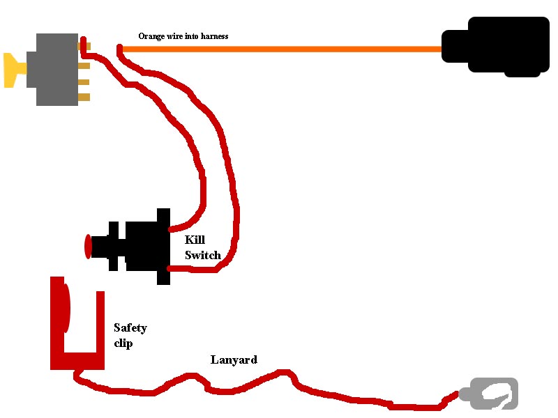
Alright, let's dive into the world of boat ignition kill switch wiring diagrams. Whether you're dealing with a faulty kill switch, customizing your boat's electrical system, or simply wanting to understand how it all works, this knowledge is crucial for any boat owner who likes to get their hands dirty. This isn't just about splicing wires; it's about safety, reliability, and knowing your vessel inside and out.
Purpose of Understanding the Wiring Diagram
Why bother understanding the boat ignition kill switch wiring diagram? Several reasons come to mind:
- Troubleshooting: A misbehaving engine? The kill switch is a prime suspect. The diagram helps you pinpoint the problem.
- Repairs: A broken wire or corroded connection? The diagram shows you exactly where to fix it.
- Customization: Adding a new kill switch or integrating it into an existing system? The diagram is your roadmap.
- Learning: Simply understanding how your boat's electrical system works empowers you to be a more confident and capable boat owner.
Key Specs and Main Parts
Before we jump into the diagram itself, let's identify the key components and their specifications. Understanding these will make the diagram much easier to interpret.
- Kill Switch (Emergency Stop Switch): This is the heart of the system. Typically, it's a normally closed (NC) switch. This means that in its default, non-activated state, the circuit is complete. When activated (the lanyard is pulled), the switch *opens*, breaking the circuit. They are often rated for a specific voltage and amperage, usually around 12V/20A for standard marine applications.
- Ignition System: This is the system the kill switch interrupts. It could be a traditional magneto ignition system or a modern electronic ignition system. The specific type will influence the wiring details. We'll assume a basic CDI (Capacitor Discharge Ignition) system for simplicity.
- Wiring Harness: The network of wires connecting everything. Marine-grade wiring is essential, as it's designed to withstand the harsh marine environment. Look for tinned copper wires to resist corrosion. Common wire gauges used are 16 AWG or 18 AWG, but this can vary depending on the current draw.
- Connectors: These are used to join wires together. Crimp connectors with heat shrink tubing are preferred for a reliable and waterproof connection.
- Fuse (Optional): While not always included *directly* in the kill switch circuit, a fuse in the main power feed to the ignition system provides crucial protection against shorts and overloads.
Symbols – Deciphering the Diagram
Wiring diagrams use standardized symbols to represent different components and connections. Here's a breakdown of the key symbols you'll encounter in a boat ignition kill switch wiring diagram:
- Straight Line: Represents a wire. A thicker line might indicate a wire with a larger gauge.
- Dot: Indicates a connection point where two or more wires are joined electrically.
- Kill Switch Symbol: This varies, but often looks like a switch with a small circle representing the activation point. It will be labeled as "Kill Switch" or "Emergency Stop". You'll typically see two states represented: Normally Closed (NC) and Normally Open (NO). The kill switch uses the NC circuit.
- Ground Symbol: Looks like a series of descending horizontal lines. Indicates a connection to the boat's grounding system. This is crucial for safety and preventing electrical shorts.
- Battery Symbol: Represents the boat's battery. Usually shown with positive (+) and negative (-) terminals.
- Fuse Symbol: A squiggly line inside a rectangle. Indicates a fuse protecting the circuit.
- Color Codes: Wires are often color-coded to aid in identification. Common colors include:
- Red: Positive (+) power.
- Black: Negative (-) or ground.
- Yellow: Often used for ignition or starter circuits.
- Blue: Can be used for various control signals.
It's crucial to note that wire colors can vary between boat manufacturers, so always double-check the diagram specific to your boat model.
How It Works
The basic principle is simple: the kill switch *interrupts* the power or signal needed to fire the engine's spark plugs. In a CDI system, the kill switch typically grounds out the CDI unit, preventing it from discharging its capacitor and firing the ignition coil.
- Normal Operation: With the lanyard attached, the kill switch is in its *normally closed* (NC) position. This completes the circuit, allowing the ignition system to function normally. The CDI unit charges its capacitor and fires the spark plugs when triggered.
- Kill Switch Activation: When the lanyard is pulled, the kill switch *opens* the circuit. This disconnects the CDI unit from its required circuit to fire the spark plugs.
- Engine Shutdown: With the circuit broken, the CDI unit can no longer discharge its capacitor, preventing the spark plugs from firing. The engine shuts down immediately.
Think of it like this: the kill switch is a gatekeeper. When the gate is closed (lanyard attached), the ignition signal can pass through. When the gate is opened (lanyard pulled), the signal is blocked, and the engine stops.
Real-World Use – Basic Troubleshooting Tips
Here are some common issues you might encounter and how to troubleshoot them using the wiring diagram:
- Engine Won't Start:
- Check the Kill Switch Position: Make sure the lanyard is properly attached and the switch is in the "run" position. Sometimes the switch itself can be faulty and stuck.
- Test for Continuity: Use a multimeter to check for continuity across the kill switch terminals when the lanyard is attached. You should see continuity (a closed circuit). When detached, there should be no continuity (an open circuit).
- Inspect Wiring: Check for broken, corroded, or loose wires and connectors in the kill switch circuit. Use the wiring diagram to trace the wires from the switch to the ignition system.
- Engine Shuts Down Unexpectedly:
- Check Lanyard: Ensure the lanyard is securely attached and isn't being accidentally pulled.
- Inspect Wiring: Look for intermittent shorts or loose connections that might be causing the kill switch circuit to open momentarily.
- Test Kill Switch: The switch may be faulty and opening intermittently, even when the lanyard is attached.
Safety – Handle with Care!
Working with electrical systems on boats can be dangerous. Here are some crucial safety precautions:
- Disconnect the Battery: Always disconnect the negative (-) battery cable before working on any electrical components. This prevents accidental shorts and shocks.
- Use Marine-Grade Components: Standard automotive parts are not designed for the harsh marine environment. Use marine-grade wiring, connectors, and switches to ensure reliability and prevent corrosion.
- Proper Grounding: Ensure all electrical components are properly grounded to the boat's grounding system. This is crucial for safety and preventing galvanic corrosion.
- Wear Safety Glasses: Protect your eyes from debris and sparks.
- If Unsure, Seek Professional Help: If you're not comfortable working with electrical systems, consult a qualified marine electrician.
The ignition system itself can be high voltage. Even with the battery disconnected, residual voltage can be present in the ignition coil or CDI unit. Discharge the system (carefully, following manufacturer's instructions) before working on it.
Now that you have a solid grasp of the boat ignition kill switch wiring diagram, you're well-equipped to tackle repairs, customizations, and troubleshooting on your own. Remember to always prioritize safety and consult a professional if you're unsure about anything.
We have a sample boat ignition kill switch wiring diagram file available for download. It provides a visual aid and can be a valuable reference tool.