Bose Spare Tire Subwoofer Wiring Diagram
So, you're diving into the world of Bose spare tire subwoofers, eh? Smart move. These systems pack a punch, delivering impressive bass without sacrificing valuable cargo space. But, like any complex audio setup, understanding the wiring is crucial. This article will be your guide to deciphering the Bose spare tire subwoofer wiring diagram. Whether you're troubleshooting a malfunction, upgrading your system, or simply curious about how it all works, knowing how to read the diagram is essential. And, good news, we have the file, and you can download the diagram to follow along.
Purpose: Why the Wiring Diagram Matters
Let's be clear: the wiring diagram isn't just a pretty picture. It's the blueprint for the entire audio system. You'll need it for:
- Repairs: Tracing shorts, identifying broken connections, and replacing faulty components.
- Upgrades: Integrating aftermarket head units, amplifiers, or speakers.
- Troubleshooting: Diagnosing audio problems like lack of bass, distortion, or complete system failure.
- Understanding: Gaining a deeper understanding of how the Bose system is designed and operates.
- DIY Projects: If you are planning to install a Bose Spare Tire Subwoofer in a car that did not come with one, it's a must have
Without a wiring diagram, you're essentially working in the dark, increasing the risk of damaging components or creating new problems.
Key Specs and Main Parts
Before we dive into the diagram itself, let's cover the core components typically found in a Bose spare tire subwoofer system:
- Subwoofer: The speaker responsible for producing low-frequency sounds (bass). It's usually a single driver, often around 5-6 inches, optimized for enclosed spaces.
- Amplifier: Powers the subwoofer. This is typically integrated within the spare tire enclosure, making it a compact unit. The amplifier specifications (wattage, impedance) are crucial for troubleshooting and matching aftermarket components.
- Wiring Harness: Connects the subwoofer/amplifier to the car's electrical system and audio source. This is where the wiring diagram comes into play.
- Connector(s): The physical interfaces where wires connect. Common types include multi-pin connectors for power, ground, signal, and remote turn-on.
- Grounding Point: A secure connection to the vehicle's chassis, providing a common reference voltage for the electrical system. A poor ground connection can cause all sorts of audio issues.
- Fuse: A safety device that protects the amplifier and wiring from overcurrent. Typically located near the power source.
Symbols: Deciphering the Diagram's Language
Wiring diagrams use standardized symbols to represent different components and connections. Understanding these symbols is key to interpreting the diagram correctly.
Lines and Colors:
- Solid Lines: Represent wires.
- Dashed Lines: Often represent shielded cables or connections that are not directly wired (e.g., CAN bus communication).
- Colors: Wires are color-coded for easy identification. The diagram will include a legend that lists the color abbreviations (e.g., RED, BLK, GRN, YEL). Note that color codes can vary slightly between vehicle models and years.
Icons:
- Resistor: A zigzag line.
- Capacitor: Two parallel lines (sometimes curved).
- Diode: A triangle pointing towards a vertical line.
- Ground: A series of decreasing horizontal lines.
- Fuse: A wavy line enclosed in a rectangle.
- Speaker: A circle with a cross inside.
- Amplifier: Usually represented by a triangle or a rectangle with input and output terminals.
- Connector: Often shown as a rectangle or circle with numbers representing the pin assignments.
Other Key Markings:
- Pin Numbers: Each wire entering a connector will have a pin number associated with it. This is critical for identifying the correct wire.
- Voltage Ratings: Some components (e.g., capacitors) may have voltage ratings indicated on the diagram.
- Wire Gauge: The thickness of the wire, usually expressed in AWG (American Wire Gauge). This is important for selecting replacement wires.
How It Works: Tracing the Signal Flow
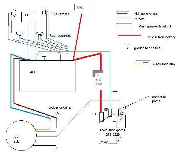
The Bose spare tire subwoofer system typically receives its audio signal from the car's head unit. The head unit outputs a low-level audio signal (RCA or speaker-level) to the amplifier located within the spare tire subwoofer enclosure. The amplifier boosts this signal and sends it to the subwoofer driver, producing the bass frequencies. A remote turn-on wire from the head unit signals the amplifier to power on when the audio system is activated. Let's break down the crucial connections:
- Power: The amplifier needs a constant 12V power supply from the car's battery. This wire is usually thick (e.g., 10-12 AWG) and protected by a fuse.
- Ground: A solid ground connection is essential for proper operation. The ground wire should be connected to a clean, unpainted metal surface on the vehicle's chassis.
- Audio Signal Input: This can be either RCA (low-level) or speaker-level inputs. The diagram will show which type of input is used.
- Remote Turn-On: This wire signals the amplifier to turn on and off with the head unit. It's typically connected to the head unit's "remote out" or "antenna" wire.
- Speaker Output: These wires connect the amplifier to the subwoofer driver. The diagram will show the polarity of the speaker connections (+ and -).
Real-World Use: Basic Troubleshooting Tips
Okay, let's say you're experiencing problems with your Bose spare tire subwoofer. Here's how to use the wiring diagram to troubleshoot:
- No Power: Check the fuse first! If the fuse is blown, replace it with one of the same amperage rating. If the new fuse blows immediately, there's likely a short circuit. Use the wiring diagram to trace the power wire and look for any damaged insulation or pinched wires.
- No Sound: Verify that the remote turn-on wire is properly connected and receiving a signal from the head unit. Use a multimeter to check for voltage on the remote turn-on wire when the head unit is on. If there's no voltage, the problem may be with the head unit or the remote turn-on wire itself. Also, check the audio signal input wires for loose connections or damage.
- Distorted Sound: This could be caused by a faulty amplifier, a damaged subwoofer driver, or a poor ground connection. Check the ground connection first, as this is a common cause of distortion. Use the wiring diagram to locate the ground point and ensure it's clean and tight.
- Intermittent Sound: This could be caused by a loose connection or a faulty component. Use the wiring diagram to inspect all connections for corrosion or damage. Gently wiggle the connectors to see if the sound cuts in and out.
Safety: Highlighting Risky Components
Working with automotive electrical systems can be dangerous if you're not careful. Keep these safety precautions in mind:
- Disconnect the Battery: Always disconnect the negative terminal of the battery before working on any electrical components. This will prevent accidental shorts and shocks.
- Work in a Well-Lit Area: Good visibility is essential for avoiding mistakes.
- Use Proper Tools: Use insulated tools designed for automotive electrical work.
- Avoid Working in Wet Conditions: Water and electricity don't mix.
- Be Careful with Capacitors: Capacitors can store electrical charge even after the battery is disconnected. Be careful when handling them.
- The Amplifier: The amplifier itself can be tricky. Although it is low voltage, improper removal and handling can create shorts.
Remember, if you're not comfortable working with electrical systems, it's always best to consult a qualified professional.
With the wiring diagram in hand and a solid understanding of the components and symbols, you'll be well-equipped to troubleshoot, repair, and upgrade your Bose spare tire subwoofer system. Happy tinkering! Just remember to take your time, double-check your connections, and prioritize safety.
As mentioned earlier, we have the file for the wiring diagram. Take your time to follow the steps to download the diagram.