
Brake Light Turn Signal Wiring Diagram
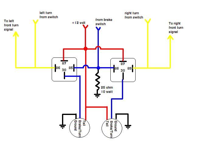
Understanding the intricacies of your vehicle's brake light and turn signal wiring might seem daunting, but it's a crucial skill for any serious DIY mechanic or automotive enthusiast. This article will guide you through the essential elements of a brake light and turn signal wiring diagram, empowering you to diagnose issues, perform repairs, and even customize your lighting systems with confidence. This knowledge is invaluable for tasks ranging from replacing a faulty bulb to troubleshooting complex electrical shorts.
Purpose of a Brake Light and Turn Signal Wiring Diagram
Why bother with a wiring diagram? Simply put, it's your roadmap to understanding the electrical system responsible for your brake lights and turn signals. These lights are critical safety features, and a malfunction can have serious consequences. A wiring diagram allows you to:
- Diagnose Malfunctions: Pinpoint the source of a problem, whether it's a blown fuse, a short circuit, or a faulty component.
- Perform Repairs: Accurately trace wires and connections to make necessary repairs without guesswork.
- Install Aftermarket Accessories: Safely and effectively integrate new lights, controllers, or other electrical components.
- Understand the System: Gain a deeper understanding of how your vehicle's electrical system operates.
Key Specifications and Main Parts
Before diving into the diagram itself, let's familiarize ourselves with the main components involved in a typical brake light and turn signal system:
- Battery: The power source for the entire system.
- Fuse Box/Panel: Contains fuses and relays that protect circuits from overloads and control power distribution. Look for fuses labeled "Turn Signal," "Brake Lights," and potentially "Hazard Lights."
- Ignition Switch: Controls power to various circuits when the key is turned on.
- Brake Light Switch: Located near the brake pedal, this switch activates the brake lights when the pedal is pressed.
- Turn Signal Switch/Multifunction Switch: Typically mounted on the steering column, this switch activates the turn signals and hazard lights.
- Flasher Unit/Relay: Causes the turn signal lights to blink on and off. These can be thermal or electronic flasher units.
- Turn Signal Bulbs (Front and Rear): Incandescent, LED, or halogen bulbs that illuminate to indicate turning direction.
- Brake Light Bulbs: Illuminate to indicate braking. Often, these are dual-filament bulbs that also serve as tail lights.
- Wiring Harness: A bundle of wires that connects all the components.
- Ground Connections: Secure connections to the vehicle's chassis, providing a return path for the electrical current. Clean grounds are essential for proper operation.
Decoding the Symbols
A wiring diagram uses specific symbols and conventions to represent electrical components and connections. Understanding these symbols is key to interpreting the diagram. Here's a breakdown of common symbols:
- Solid Lines: Represent wires connecting different components. The thickness of the line doesn't usually indicate wire gauge.
- Dashed Lines: May indicate connections that are optional or only present in certain vehicle configurations.
- Circles: Often represent bulbs or lamps.
- Rectangles: Can represent switches, relays, or control modules.
- Resistor Symbol (Zig-zag line): Indicates a resistor used to limit current flow.
- Ground Symbol (Series of descending lines): Represents a connection to the vehicle's chassis, providing a return path for the current.
- Fuse Symbol: A squiggly line inside a rectangle or a small box.
- Relay Symbol: Shows a coil and a set of contacts that switch when the coil is energized.
- Color Codes: Wires are typically color-coded to aid in identification. Common colors include Black (BLK) for ground, Red (RED) for power, and various other colors for specific circuits. The diagram will usually include a legend explaining the color codes used. For instance, "GRN" might represent a green wire.
- Numerical Labels: May be used to identify specific wires or terminals on components.
Pay close attention to the legend on the wiring diagram, as it will provide crucial information about the symbols and abbreviations used.
How It Works: A Simplified Circuit
Let's trace a simplified brake light circuit to illustrate how the system operates:
- Power flows from the battery, typically through a fuse in the fuse box.
- The power then travels to the brake light switch, which is normally open (no connection).
- When the brake pedal is pressed, the brake light switch closes, completing the circuit.
- Power flows from the brake light switch to the brake light bulbs.
- The bulbs illuminate, and the current flows back to the battery through a ground connection.
The turn signal circuit is more complex because it involves the flasher unit and the turn signal switch. The turn signal switch directs power to either the left or right turn signal bulbs, while the flasher unit interrupts the power flow to create the blinking effect.
Real-World Use: Basic Troubleshooting Tips
Here are some common problems and how a wiring diagram can help:
- Brake Lights Don't Work: Check the brake light fuse first. If the fuse is blown, replace it. If it blows again immediately, there's a short circuit in the brake light circuit. Use the wiring diagram to trace the wires and identify the location of the short. Also check the brake light switch itself. A faulty switch is a common culprit.
- Turn Signals Don't Work: Check the turn signal fuse. If both turn signals are out, the flasher unit is likely the problem. If only one side is out, check the bulbs and the wiring connections to the affected side. The wiring diagram will help you identify the correct wires to test.
- Turn Signals Blink Too Fast (Hyperflashing): This usually indicates a burned-out bulb on that side. The increased resistance causes the flasher to blink faster. Replacing the bulb should resolve the issue. LED replacements can also cause this issue.
When troubleshooting, always use a multimeter to check for voltage and continuity. A multimeter is an indispensable tool for any automotive electrical work.
Safety Considerations
Working with automotive electrical systems can be dangerous. Here are some crucial safety precautions:
- Disconnect the Battery: Always disconnect the negative battery terminal before working on any electrical system. This prevents accidental shorts and electrical shocks.
- Work in a Well-Ventilated Area: Batteries can produce explosive gases.
- Use Proper Tools: Use insulated tools designed for electrical work.
- Be Careful with Wiring: Avoid cutting or damaging wires unnecessarily.
- Replace Fuses with the Correct Amperage: Never use a fuse with a higher amperage rating than specified, as this can damage the wiring and create a fire hazard.
- The Flasher Unit Capacitor: Some flasher units contain a capacitor that can hold a charge even after the battery is disconnected. Discharge the capacitor before handling the unit. This is usually done by connecting a resistor across the capacitor terminals. Refer to the manufacturer's instructions for proper discharge procedures.
Components like the battery and the flasher unit can pose specific risks if not handled correctly. Always exercise caution and follow safety guidelines.
You can download a sample brake light and turn signal wiring diagram to further enhance your understanding. This diagram will serve as a valuable reference tool for your future automotive projects.