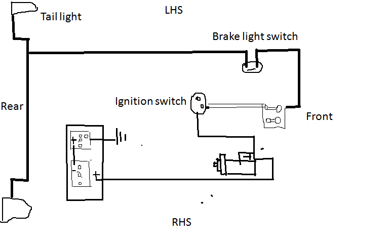
Brake Pedal Switch Simple Brake Light Circuit Diagram
Understanding the brake light circuit is fundamental for any car owner, especially those who dabble in DIY repairs or modifications. A malfunctioning brake light isn't just a ticket waiting to happen; it's a serious safety hazard. This article breaks down a simple brake light circuit diagram, providing you with the knowledge to troubleshoot problems, perform basic repairs, and understand how this essential system works.
Purpose of Understanding the Brake Light Circuit
Why should you care about a brake light circuit diagram? There are several key reasons:
- Troubleshooting: When your brake lights aren't working, a diagram helps you systematically trace the circuit to identify the faulty component, whether it's the switch, wiring, bulbs, or fuses.
- Repair and Replacement: Knowing the circuit layout allows you to safely replace damaged wires, connectors, or the brake pedal switch itself.
- Modification and Customization: If you're adding auxiliary brake lights, aftermarket tail lights, or other lighting enhancements, understanding the existing circuit is crucial to avoid overloading the system or creating shorts.
- Learning Automotive Electrical Systems: The brake light circuit is a relatively simple example of a basic automotive electrical circuit, making it an excellent starting point for learning more about how your car's electrical system works.
Key Specs and Main Parts
A typical brake light circuit is surprisingly straightforward. The main components include:
- Battery: The source of electrical power (typically 12V DC).
- Fuse: A safety device designed to protect the circuit from overcurrent. If the current exceeds the fuse's rating, the fuse blows (the filament melts), interrupting the circuit and preventing damage. Common fuse ratings for brake light circuits are 10A to 20A.
- Brake Pedal Switch: A simple on/off switch activated by depressing the brake pedal. When the pedal is pressed, the switch closes, completing the circuit.
- Wiring: Conductors (typically copper wires) that carry the electrical current. Wire gauge (thickness) is important; too thin, and the wire can overheat. The correct gauge is specified in the vehicle's service manual.
- Brake Light Bulbs: Incandescent bulbs or LEDs that illuminate when the circuit is complete. Bulb wattage is crucial; using a bulb with a higher wattage than specified can overload the circuit and blow the fuse.
- Ground: The return path for the electrical current, connected to the vehicle's chassis. A good ground connection is essential for proper circuit operation. Corrosion or loose connections can cause problems.
Symbols and Conventions in the Circuit Diagram
Understanding the symbols used in the diagram is crucial for interpreting it correctly.
- Straight Lines: Represent wires. Thicker lines may indicate heavier gauge wire.
- Battery Symbol: Depicted as a series of alternating long and short lines. The longer line represents the positive (+) terminal, and the shorter line represents the negative (-) terminal (ground).
- Fuse Symbol: Often depicted as a squiggly line inside a rectangle or a simple rectangle.
- Switch Symbol: Shows a break in the circuit that can be closed by activating the switch. The brake pedal switch will be in the open position until the pedal is depressed.
- Bulb Symbol: Resembles a circle with an "X" inside or a stylized filament.
- Ground Symbol: Represented by a series of downward-pointing lines, often resembling an upside-down Christmas tree.
- Color Coding: Wires are often color-coded (e.g., red for power, black for ground). Refer to your vehicle's wiring diagram for the specific color codes used in your brake light circuit.
Note: Circuit diagrams can vary slightly in their representation of components, so always refer to the specific diagram for your vehicle.
How the Brake Light Circuit Works
The brake light circuit is a simple series circuit. Here's how it operates:
- Power flows from the battery to the fuse, protecting the circuit from overloads.
- From the fuse, the power travels to the brake pedal switch.
- When the brake pedal is not depressed, the switch is open, and the circuit is incomplete. No current flows.
- When the brake pedal is depressed, the switch closes, completing the circuit.
- Current flows through the closed switch to the brake light bulbs.
- The current energizes the filaments (or LEDs) in the bulbs, causing them to illuminate.
- The current then flows from the bulbs to the ground connection, completing the circuit and returning to the battery.
Real-World Use: Basic Troubleshooting
Here's how to use your understanding of the circuit to troubleshoot common brake light problems:
- No Brake Lights:
- Check the fuse first. A blown fuse is the most common cause. Replace it with a fuse of the same amperage. If it blows again immediately, there's a short circuit.
- Check the brake light bulbs. Replace any burnt-out bulbs.
- Test the brake pedal switch. Use a multimeter to check for continuity when the pedal is depressed. If there's no continuity, the switch is faulty.
- Check the ground connections. Ensure they are clean and tight. Corrosion can prevent proper grounding.
- Inspect the wiring for damage or loose connections.
- One Brake Light Works, the Other Doesn't:
- Check the bulb of the non-working light.
- Check the bulb socket for corrosion or damage.
- Inspect the wiring to the non-working light for breaks or loose connections.
- Brake Lights Stay On:
- The brake pedal switch may be stuck in the closed position. Try tapping the switch to see if it releases.
- The switch may be misadjusted. Adjust the switch so it's only activated when the pedal is depressed.
Safety Considerations
Working with automotive electrical systems involves inherent risks. Consider the following:
- Battery: Always disconnect the negative battery cable before working on any electrical circuit. This prevents accidental shorts and potential electrical shock.
- Fuses: Never replace a fuse with one of a higher amperage. This can overload the circuit and cause a fire.
- Wiring: Use properly insulated tools and avoid working on electrical systems in wet conditions.
- Bulbs: Allow bulbs to cool before handling them. Hot bulbs can cause burns.
- Short Circuits: Be extremely careful when testing for shorts. A direct short to ground can cause sparks and damage to the electrical system.
Caution: If you are uncomfortable working with electrical systems, consult a qualified mechanic. Improper repairs can lead to further damage or safety hazards.
Conclusion
Understanding the brake light circuit is a valuable skill for any car enthusiast or DIY mechanic. By familiarizing yourself with the components, symbols, and troubleshooting techniques outlined in this article, you can confidently diagnose and repair brake light issues, ensuring your safety and the safety of others on the road. Remember to always prioritize safety and consult a professional if you're unsure about any aspect of the repair process. With the brake light circuit diagram, simple brake light circuit troubleshooting and repair become accessible.
We have a simple brake light circuit diagram file that you can download for easier access and reference. Contact us to get the file.