Brake System Ford F150 Brake Lines Diagram
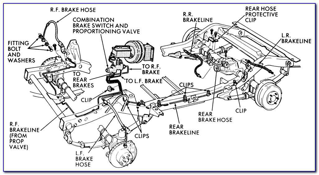
Understanding the brake system in your Ford F-150 is crucial for both routine maintenance and more involved repairs. A brake line diagram is an indispensable tool, acting as a roadmap to navigating this complex system. This article will guide you through the intricacies of a Ford F-150 brake line diagram, empowering you to tackle brake-related issues with confidence.
Purpose of the Brake Line Diagram
A brake line diagram serves several important purposes:
- Repair and Replacement: It provides a visual guide for identifying and replacing damaged or corroded brake lines. Accurate routing is critical for proper brake function.
- Troubleshooting: The diagram helps trace leaks and diagnose system failures by showing the location of all components and their connections.
- Modification and Upgrades: If you're upgrading your brake system with aftermarket components, the diagram will help you understand the existing system layout and ensure compatibility.
- Learning and Understanding: Even if you're not actively working on your brakes, the diagram can enhance your understanding of how the system operates.
Having access to and understanding the diagram can save you time, money, and potential headaches by enabling you to perform tasks yourself or better communicate with a professional mechanic.
Key Specs and Main Parts of the F-150 Brake System
Before diving into the diagram, let's review the core components of a typical F-150 brake system. While specific configurations may vary depending on the model year, trim, and options (like ABS), the fundamental principles remain the same.
- Master Cylinder: Located under the hood, typically near the firewall, the master cylinder is the heart of the system. It converts the mechanical force from the brake pedal into hydraulic pressure. It contains reservoirs for brake fluid and pistons that pressurize the fluid when the brake pedal is depressed.
- Brake Booster: This vacuum-assisted device amplifies the force applied to the brake pedal, making it easier to stop the truck. It's typically located between the brake pedal and the master cylinder.
- Brake Lines: These are the metal or flexible hoses that carry brake fluid under pressure from the master cylinder to the brake calipers and wheel cylinders. Steel lines are common for long runs, while flexible lines are used near the wheels to accommodate suspension movement.
- Brake Calipers (Front): These house the brake pads and pistons that clamp onto the brake rotors when the brake pedal is applied. Hydraulic pressure forces the pistons to press the brake pads against the rotor, creating friction and slowing the wheel.
- Brake Rotors (Front): These are the metal discs that rotate with the wheels. The calipers clamp onto the rotors to create friction and stop the vehicle.
- Wheel Cylinders (Rear): (For models with rear drum brakes). Similar to calipers, wheel cylinders use hydraulic pressure to push brake shoes against the inside of the brake drums.
- Brake Drums (Rear): (For models with rear drum brakes). These are cylindrical housings that rotate with the wheels. Brake shoes inside the drums create friction to stop the vehicle.
- Brake Pads and Shoes: These friction materials are pressed against the rotors or drums to slow the vehicle. They wear down over time and need to be replaced.
- Anti-lock Braking System (ABS) Module: A critical safety component that prevents wheel lockup during hard braking. It modulates the pressure to each wheel individually to maintain traction. The ABS module contains valves and sensors that regulate brake pressure.
- Proportioning Valve: Regulates the hydraulic pressure between the front and rear brakes to prevent rear wheel lockup during braking. This ensures balanced braking performance.
- Brake Fluid Reservoir: Part of the master cylinder assembly. It holds the brake fluid supply.
Understanding Symbols in the Brake Line Diagram
Brake line diagrams use standardized symbols to represent different components and connections. Here's a breakdown of common symbols you'll encounter:
- Lines: Solid lines represent rigid brake lines, while dashed lines may represent flexible brake hoses. Line thickness might indicate the diameter of the line.
- Arrows: Indicate the direction of brake fluid flow.
- Circles/Dots: Represent connections or junctions in the brake lines.
- Squares/Rectangles: Typically represent components like the master cylinder, ABS module, or proportioning valve.
- Letters/Abbreviations: Used to label specific components or connections (e.g., "MC" for master cylinder, "FR" for front right wheel).
- Colors: Some diagrams use colors to differentiate between different circuits or types of fluid lines. For example, a blue line may indicate the front brake circuit, while a red line indicates the rear brake circuit. Always refer to the diagram's legend to understand the color coding.
Pay close attention to the legend or key accompanying the diagram, as it will provide specific definitions for the symbols used. Different manufacturers might use slightly different symbols, so always consult the legend first.
How the F-150 Brake System Works
The F-150 brake system operates on a hydraulic principle. When you press the brake pedal, the following sequence of events occurs:
- The brake pedal pushes the piston in the master cylinder.
- The piston pressurizes the brake fluid in the master cylinder.
- The pressurized brake fluid travels through the brake lines to the calipers (front) and wheel cylinders (rear, if equipped).
- In the front calipers, the pressurized fluid forces the caliper pistons to clamp the brake pads against the rotors, creating friction and slowing the wheels.
- In the rear (if drum brakes are present), the pressurized fluid forces the wheel cylinder pistons to push the brake shoes against the drums, creating friction and slowing the wheels.
- The ABS module monitors wheel speed and intervenes if it detects wheel lockup. It rapidly modulates the pressure to individual wheels to maintain traction and prevent skidding.
- The proportioning valve helps to balance the braking force between the front and rear wheels, preventing rear wheel lockup, especially during hard braking.
The brake lines are a critical pathway for this hydraulic system. Any leaks, blockages, or damage to the lines can significantly impair braking performance.
Real-World Use: Basic Troubleshooting Tips
The brake line diagram can be invaluable for troubleshooting brake problems. Here are a few common scenarios:
- Brake Fluid Leak: Use the diagram to trace the brake lines from the master cylinder to each wheel. Check for wet spots, drips, or corrosion, which could indicate a leak. Start by checking connections and fittings.
- Soft or Spongy Brake Pedal: This could be caused by air in the brake lines. Use the diagram to identify the bleed screws on each caliper and wheel cylinder. Bleeding the brakes will remove the air.
- Uneven Braking: If your truck pulls to one side during braking, it could be due to a problem with one of the brake calipers or wheel cylinders. Use the diagram to isolate the affected side and inspect the components. Check brake pad wear for any inconsistencies.
- ABS Light On: The ABS light indicates a problem with the ABS system. While the brake line diagram won't directly diagnose the cause, it will help you understand the location of the ABS module and related components, aiding in further diagnostics. You'll typically need an OBD-II scanner capable of reading ABS codes to pinpoint the problem.
Always consult a repair manual specific to your F-150 model year for detailed troubleshooting procedures and torque specifications.
Safety Considerations
Working on brake systems involves inherent risks. Brake fluid is corrosive and can damage paint. Here are some key safety precautions:
- Brake Fluid: Wear eye protection and gloves when handling brake fluid. Avoid getting it on your skin or in your eyes. If contact occurs, flush immediately with water.
- High Pressure: The brake system is under high pressure. Before disconnecting any brake lines, relieve the pressure by bleeding the brakes.
- Contamination: Keep brake fluid clean and uncontaminated. Never reuse old brake fluid.
- Torque Specifications: Always tighten brake line fittings to the specified torque. Overtightening can damage the fittings, while undertightening can lead to leaks. Refer to your repair manual for the correct torque values.
- Air in the System: Air in the brake lines can severely compromise braking performance. After working on the brake system, bleed the brakes thoroughly to remove any air.
- Double-Check Your Work: Before driving the vehicle, carefully inspect all connections and ensure that there are no leaks. Pump the brake pedal several times to verify that the brakes are functioning properly.
- The ABS module is electrically sensitive. Disconnect the negative battery terminal before working on or around it.
Important Note: Improper brake repairs can lead to serious accidents. If you are not comfortable working on your brake system, it's best to consult a qualified mechanic. The master cylinder and ABS module are particularly sensitive components. Improper handling can render them useless, necessitating expensive replacements.
We have a comprehensive Ford F-150 brake line diagram available for download. This diagram will provide you with the visual aid you need to confidently tackle brake-related tasks. Please contact us to obtain the file.