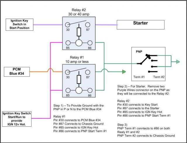
Bypass Gm Neutral Safety Switch Wiring Diagram
Let's dive into a topic that often comes up when dealing with older GM vehicles, or when you're facing some particularly frustrating electrical gremlins: bypassing the GM neutral safety switch. Before we proceed, a very important disclaimer: Bypassing safety mechanisms should *never* be taken lightly. This information is for diagnostic and emergency situations only. Always ensure the vehicle is in Park or Neutral and the parking brake is engaged before starting, and consult a professional mechanic for permanent repairs. Misusing this information could lead to serious injury or damage.
Purpose of a Neutral Safety Switch (NSS) Wiring Diagram
Understanding the NSS wiring diagram is crucial for several reasons:
- Troubleshooting Starting Issues: When your GM vehicle refuses to crank, the NSS is a prime suspect. The diagram helps pinpoint breaks in the circuit.
- Performing Emergency Starts: In a situation where the NSS has failed completely and leaves you stranded, knowing how to bypass it *temporarily* can get you moving (again, with extreme caution).
- Understanding the Electrical System: Even if you're not planning to bypass anything, studying the diagram deepens your knowledge of the vehicle's overall electrical architecture.
- Modifications and Swaps: If you're swapping transmissions or making other modifications, you might need to understand the NSS wiring to integrate it properly with the new setup.
Key Specs and Main Parts of the NSS Circuit
The neutral safety switch, also sometimes called a transmission range sensor (TRS), is usually mounted on the transmission, either internally or externally, depending on the model. Its primary function is to prevent the engine from starting unless the transmission is in Park or Neutral. Here's a breakdown of the main components:
- Neutral Safety Switch (NSS): The heart of the system. It contains contacts that close only when the transmission is in Park or Neutral, allowing the starter circuit to complete.
- Starter Solenoid: This is an electromagnet that engages the starter motor when energized. It receives power from the NSS when the switch is in the correct position.
- Starter Motor: The actual motor that cranks the engine.
- Ignition Switch: Provides the initial signal to start the vehicle.
- Wiring Harness: The network of wires connecting all the components. These wires carry the electrical signals that make the system work.
- Fuses and Relays: Provide protection and amplification of the electrical signals.
Key Specs to be aware of usually include the wiring gauge (typically 12-16 gauge for the starter circuit), the voltage (12V DC in most cases), and the current draw of the starter solenoid (which can be significant, around 30-50 amps). Knowing these values is essential for troubleshooting and ensuring any bypass wiring you might use is properly sized.
Decoding the Symbols: Wiring Diagram Language
Wiring diagrams use a standardized set of symbols to represent electrical components and connections. Here's a quick guide:
- Solid Lines: Represent wires. Thicker lines usually indicate wires carrying higher current.
- Dashed Lines: Often represent ground connections.
- Circles: Can represent various components, depending on what's inside them. A circle with a resistor symbol indicates a resistor. A circle with a coil symbol indicates a relay coil or inductor.
- Squares: Often represent switches or relays. The position of the switch contacts indicates the state of the switch (open or closed).
- Ground Symbol: Looks like a series of downward-pointing lines, indicating a connection to the vehicle's chassis ground.
- Colors: Wires are often color-coded to help identify them. Common colors include red (power), black (ground), yellow, green, blue, brown, and white. Each color typically has a specific function within the circuit.
Example: A thick, solid red line connected to a battery symbol likely represents the main power wire to the ignition switch.
Understanding the specific GM wiring diagram you're using is vital. GM's wiring diagrams changed over the years, so a diagram for a 1980s truck will be different from a diagram for a 2000s car. Always refer to the correct diagram for your specific year, make, and model.
How the NSS Circuit Works
The NSS circuit is relatively simple. Here's a step-by-step explanation:
- Ignition Switch Activation: When you turn the ignition key to the "Start" position, the ignition switch sends a signal to the NSS.
- NSS Check: The NSS verifies that the transmission is in Park or Neutral. If it is, the internal contacts within the switch close, completing the circuit.
- Starter Solenoid Engagement: The closed NSS contacts allow power to flow to the starter solenoid.
- Starter Motor Activation: The energized starter solenoid engages the starter motor, which then cranks the engine.
- Engine Start: Once the engine starts, you release the key, and the ignition switch returns to the "Run" position. The NSS is no longer needed to keep the engine running.
If the NSS is faulty or the transmission is not in Park or Neutral, the circuit remains open, preventing the starter solenoid from engaging and the engine from cranking. This is a crucial safety feature to prevent the vehicle from unexpectedly lurching forward or backward when started.
Real-World Use: Basic Troubleshooting
Here are some basic troubleshooting tips using the NSS wiring diagram:
- No Crank, No Start: If the engine doesn't crank at all, check the NSS first. Use a multimeter to test for voltage at the starter solenoid when the key is in the "Start" position. If there's no voltage, trace the circuit back to the NSS.
- Intermittent Starting: Sometimes, the engine starts intermittently. This could indicate a loose connection at the NSS or a worn-out switch. Try wiggling the shift lever in Park or Neutral while trying to start the engine. If it starts, the NSS is likely the culprit.
- Testing the NSS: Use a multimeter to check the continuity of the NSS contacts when the transmission is in Park and Neutral. The contacts should be closed (showing continuity). When the transmission is in any other gear, the contacts should be open (no continuity).
- Bypassing for Diagnostic Purposes: (Again, use extreme caution!) You can temporarily bypass the NSS by connecting the two wires that lead to the starter solenoid together. This directly energizes the solenoid and bypasses the safety interlock. If the engine starts when you do this, it confirms that the NSS is the problem. Never drive the vehicle with the NSS bypassed permanently.
Safety Precautions
Working with electrical systems in a vehicle can be dangerous. Here are some crucial safety precautions:
- Disconnect the Battery: Before working on any electrical circuit, disconnect the negative battery cable to prevent accidental shorts and shocks.
- Use Proper Tools: Use insulated tools designed for automotive electrical work.
- Avoid Working in Wet Conditions: Water conducts electricity, so avoid working on the electrical system in wet or damp conditions.
- Be Aware of Airbag Systems: Some vehicles have airbag sensors and wiring near the NSS. Be extremely careful not to damage these components, as it could cause the airbags to deploy accidentally.
- Never Permanently Bypass Safety Features: The NSS is there for a reason. Never permanently bypass it, as it could lead to serious accidents.
The most risky components are obviously the starter motor itself, which draws a huge amount of current, and the battery. Even a small short circuit close to the battery can cause a fire. Always double-check your wiring before reconnecting the battery.
This information should give you a solid foundation for understanding the GM neutral safety switch wiring diagram. Remember to always consult the correct diagram for your specific vehicle and prioritize safety.
We have the complete wiring diagram file ready for you to download. Please reach out through the contact form, and we'll be happy to provide it.