
Cam 3 Wire Crank Sensor Wiring Diagram
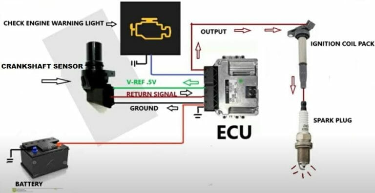
Understanding your car's engine management system is crucial for both preventative maintenance and troubleshooting. One vital component in that system is the crankshaft position sensor (CKP), and specifically the 3-wire version. This article delves into the 3-wire CKP sensor wiring diagram, providing you with the knowledge to diagnose issues, perform repairs, or even undertake performance modifications with confidence. We'll break down the diagram's purpose, key components, symbols, operation, real-world use, and essential safety considerations.
Purpose of Understanding the 3-Wire CKP Sensor Wiring Diagram
Why bother learning about this diagram? Several reasons stand out:
- Diagnostics and Repair: A malfunctioning CKP sensor can cause a no-start condition, rough idling, or poor engine performance. The wiring diagram helps you pinpoint whether the problem lies within the sensor itself, the wiring harness, or the engine control unit (ECU).
- Performance Modifications: When upgrading your engine with performance parts (e.g., aftermarket ECU), understanding the CKP sensor wiring is essential for proper integration and tuning.
- Learning Engine Management: Studying the diagram provides a deeper understanding of how the engine management system utilizes the CKP sensor signal for fuel injection timing, ignition timing, and other critical functions.
- Preventative Maintenance: By understanding the wiring, you can inspect for common issues like frayed wires, corroded connectors, and shorts before they lead to major problems.
Key Specs and Main Parts of a 3-Wire CKP Sensor System
Before diving into the diagram, let's define the key components involved:
- Crankshaft Position Sensor (CKP): This is the sensor itself. It's usually a Hall-effect sensor or a magnetic reluctance sensor. It detects the position of the crankshaft, typically by reading teeth on a reluctor wheel or tone ring attached to the crankshaft.
- Reluctor Wheel/Tone Ring: A toothed wheel attached to the crankshaft. The sensor reads the passing teeth to determine crankshaft position. The number of teeth, and any missing teeth (a "gap"), is critical for the ECU to accurately calculate engine speed and position.
- Wiring Harness: The set of wires connecting the CKP sensor to the ECU and other components.
- Engine Control Unit (ECU): The "brain" of the engine management system. It receives the CKP sensor signal and uses it to control fuel injection, ignition timing, and other engine functions.
- Connector: The physical connector that plugs into the CKP sensor. This is a common point of failure due to corrosion or damage.
Key Specs to Consider:
- Sensor Type: Hall-effect or magnetic reluctance. This affects the sensor's voltage output and signal characteristics.
- Voltage: Typically 5V or 12V, depending on the vehicle.
- Resistance: Some diagrams might include resistance values for the sensor windings (if applicable). This is useful for diagnosing internal sensor failures.
- Waveform: The CKP sensor generates a specific waveform (typically a square wave or sine wave). Observing this waveform with an oscilloscope is a crucial diagnostic step.
Symbols in the 3-Wire CKP Sensor Wiring Diagram
Wiring diagrams use standardized symbols to represent different components and connections. Here's a breakdown of common symbols found in a 3-wire CKP sensor diagram:
- Lines: These represent wires. Solid lines indicate a direct connection, while dashed lines might indicate a shielded wire or a ground connection. The thickness of the line usually has no significance.
- Colors: Wires are color-coded (e.g., red, black, blue, green). The diagram will include a legend identifying the color of each wire. Always refer to the legend; don't assume colors are consistent across all vehicles.
- Ground Symbol (⏚): Indicates a connection to the vehicle's chassis ground. This is often a black wire.
- Voltage Supply Symbol (V+ or B+): Indicates a connection to the vehicle's battery voltage (typically 12V) or a regulated 5V supply.
- ECU Symbol: A rectangle or square representing the Engine Control Unit. The diagram will show which pins on the ECU connect to the CKP sensor wires.
- Connector Symbol: Usually represented as interlocking shapes or rectangles. The diagram might show the pin numbers on the connector.
- Sensor Symbol: A stylized representation of the CKP sensor itself.
Typically, in a 3-wire CKP sensor system, you'll find the following wires:
- Power Supply Wire: Provides voltage to the sensor (typically 5V or 12V).
- Ground Wire: Completes the circuit, providing a return path for the current.
- Signal Wire: Carries the crankshaft position signal to the ECU. This is the most important wire for diagnostics.
How the 3-Wire CKP Sensor System Works
The CKP sensor works by detecting changes in the magnetic field as the reluctor wheel rotates. Here's a simplified explanation:
- The reluctor wheel, with its teeth, rotates along with the crankshaft.
- As a tooth passes the sensor, it disrupts the magnetic field generated by the sensor's internal components.
- In a Hall-effect sensor, this change in magnetic field causes a change in voltage on the signal wire. In a magnetic reluctance sensor, the passing tooth induces a voltage in the sensor's coil.
- The sensor sends this varying voltage signal to the ECU.
- The ECU interprets the frequency and pattern of the signal to determine the crankshaft's position and speed. The ECU uses this information to control fuel injection timing, ignition timing, and other engine functions.
Real-World Use: Basic Troubleshooting Tips
Here are some basic troubleshooting steps using the wiring diagram:
- Visual Inspection: Check the wiring harness and connector for any signs of damage (frayed wires, cracked insulation, corroded terminals).
- Continuity Test: Use a multimeter to check the continuity of each wire between the sensor connector and the ECU connector. A lack of continuity indicates a broken wire.
- Voltage Test: Use a multimeter to check for the correct voltage on the power supply wire (typically 5V or 12V). A lack of voltage indicates a problem with the power supply circuit.
- Signal Wire Test: Use an oscilloscope to observe the waveform on the signal wire while the engine is cranking or running. A missing or distorted waveform indicates a problem with the sensor, the reluctor wheel, or the wiring. A multimeter, set to AC voltage, can also be used but it gives a less precise reading. You should see a fluctuating AC voltage as the engine cranks.
- Resistance Test: Check the resistance of the sensor itself (if specifications are available). An incorrect resistance value indicates a faulty sensor.
Example Scenario: Your car won't start. You suspect a CKP sensor issue. You consult the wiring diagram and identify the power, ground, and signal wires. You use a multimeter to check for 5V on the power wire and continuity to ground on the ground wire. Both check out. You then use an oscilloscope to check the signal wire while cranking the engine. You see no signal. This strongly suggests a faulty CKP sensor, a damaged reluctor wheel, or a break in the signal wire *between* the sensor connector and the ECU, despite the earlier continuity test.
Safety Considerations
Working on automotive electrical systems involves potential hazards. Keep these points in mind:
- Disconnect the Battery: Always disconnect the negative battery terminal before working on any electrical component. This prevents accidental shorts and electrical shocks.
- High Voltage Components: Be extremely cautious around ignition components (spark plugs, ignition coils) as they carry high voltage.
- Fuel System: Be aware of the proximity of the fuel system. Avoid sparks or open flames when working near fuel lines or fuel injectors.
- Proper Tools: Use appropriate tools for the job. Use insulated tools when working on electrical circuits.
- Consult the Service Manual: Always refer to the vehicle's service manual for specific instructions and warnings.
Risk Highlight: The ECU itself is a sensitive electronic component. Never probe ECU pins with excessive force or use incorrect testing procedures, as you could damage the ECU. Double-check your connections and measurements before applying power.
By understanding the 3-wire CKP sensor wiring diagram, you empower yourself to diagnose and repair engine problems, perform performance modifications, and gain a deeper understanding of your car's engine management system. Remember to prioritize safety and consult the vehicle's service manual for specific information.
We have a sample 3-Wire CKP Sensor Wiring Diagram file available for download. This diagram provides a visual aid and further reinforces the concepts discussed in this article. It includes typical wire colors, pin assignments, and component locations. Click the download link below to access the file.
Download 3-Wire CKP Sensor Wiring Diagram (Link Placeholder)