
Camshaft Position Sensor Wiring Diagram
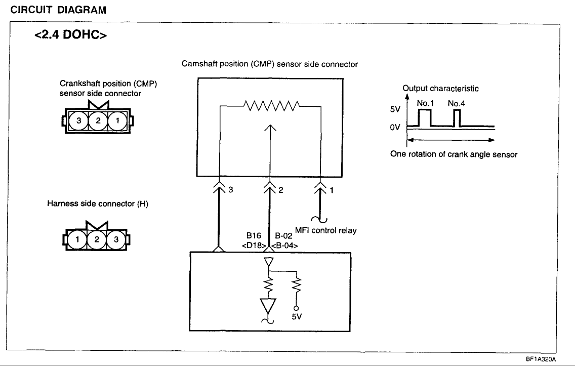
Hey gearheads! Ever find yourself staring at a camshaft position sensor (CMP sensor) wiring diagram and feeling like you're trying to decipher ancient hieroglyphics? Don't worry, you're not alone. This article is designed to demystify CMP sensor wiring diagrams, giving you the knowledge to confidently diagnose issues, perform repairs, and even undertake engine modifications with a deeper understanding. Think of this as your personal guide to understanding the nervous system of your engine's timing.
Why a CMP Sensor Wiring Diagram Matters
A CMP sensor wiring diagram isn't just a piece of paper; it's your roadmap to understanding how the CMP sensor communicates with the engine control unit (ECU). The ECU, also known as the engine computer, relies heavily on the signal from the CMP sensor. This signal is critical for:
- Engine Starting: The ECU needs to know the camshaft position to time the fuel injection and ignition correctly for starting.
- Fuel Injection Timing: Precise fuel injection timing is crucial for optimal fuel economy and power.
- Ignition Timing: The ECU adjusts ignition timing based on camshaft position for efficient combustion.
- Diagnostics: When things go wrong, the ECU uses the CMP sensor signal to diagnose issues and trigger diagnostic trouble codes (DTCs), which you'll see as a check engine light.
Understanding the wiring diagram allows you to:
- Troubleshoot electrical problems: Identify shorts, opens, and bad connections.
- Verify sensor functionality: Check voltage and resistance readings to ensure the sensor is working correctly.
- Perform sensor replacements: Ensure proper wiring during installation.
- Modify or upgrade your engine: Understand how aftermarket components integrate with the existing system.
Key Specs and Main Parts of a CMP Sensor Circuit
Before diving into the diagram itself, let's familiarize ourselves with the key components and their specifications. A typical CMP sensor circuit consists of:
- CMP Sensor: This is the star of the show. Most modern CMP sensors are Hall-effect sensors. These sensors generate a digital signal (on/off) based on the position of a reluctor wheel (a toothed wheel) on the camshaft. Some older vehicles may use magnetic pickup sensors, which produce an analog signal (varying voltage).
- ECU (Engine Control Unit): The brain of the operation. It receives the signal from the CMP sensor and uses it to control various engine functions.
- Wiring Harness: The network of wires that connects the CMP sensor to the ECU, and often includes connections to the vehicle's power and ground systems.
- Connectors: These provide a secure and reliable connection between the sensor, wiring harness, and ECU.
- Fuses: These are safety devices that protect the circuit from overcurrent. A blown fuse in the CMP sensor circuit will almost certainly cause problems.
Common CMP Sensor Types:
- Hall-Effect Sensor: Requires power (typically 5V or 12V), ground, and a signal wire. Output is a digital square wave.
- Magnetic Pickup Sensor: Has two wires, one providing a sinusoidal AC voltage signal to the ECU.
Decoding the Symbols: Reading the Wiring Diagram
Wiring diagrams use standardized symbols to represent components and wiring connections. Here's a breakdown of common symbols you'll encounter:
- Lines: Represent wires. Solid lines typically indicate a direct connection, while dashed lines might represent a shielded wire or a connection that is not always present. The thickness of the line sometimes indicates the wire gauge (thicker lines mean thicker wires).
- Colors: Each wire is assigned a color code (e.g., RED, BLU, GRN, BLK). This helps you identify the specific wire in the harness. Color codes are usually abbreviated.
- Circles/Dots: Indicate wire splices or connections.
- Rectangles: Represent components like the ECU or relays.
- Ground Symbol: Looks like a downward-pointing triangle or a series of horizontal lines getting smaller. Indicates a connection to the vehicle's chassis ground.
- Fuse Symbol: A wavy line inside a rectangle.
- Connector Symbol: Often shown as a square with pins labeled.
Understanding the Flow: The diagram typically shows the power source (battery) at the top and ground at the bottom. Trace the lines from the power source, through the fuse, to the sensor, and then back to the ECU and ground to understand the circuit's path.
Example: A diagram might show a RED wire (likely +12V or +5V) running from the ignition switch, through a fuse, and then to pin 1 of the CMP sensor. A BLK wire (ground) would connect to pin 2 of the sensor and then to the chassis ground. A GRN wire (signal) would connect to pin 3 of the sensor and then to a specific pin on the ECU.
How the CMP Sensor Circuit Works
Let's break down how the CMP sensor circuit functions:
- Power Supply: The ECU or another source provides power (typically 5V or 12V) to the CMP sensor.
- Camshaft Rotation: As the camshaft rotates, the reluctor wheel passes by the CMP sensor.
- Signal Generation (Hall-Effect): As each tooth on the reluctor wheel passes, the magnetic field disrupts the Hall-effect sensor. This creates an "on/off" digital signal (a square wave).
- Signal Transmission: The CMP sensor sends this signal to the ECU via the signal wire.
- ECU Processing: The ECU interprets the signal, determines the camshaft position, and uses this information to control fuel injection and ignition timing.
The frequency of the signal changes with the engine RPM. The ECU uses this frequency to determine the engine speed and adjust timing accordingly.
Real-World Use: Basic Troubleshooting
Here are some basic troubleshooting tips using the wiring diagram:
- Check Engine Light: If you have a check engine light and a DTC related to the CMP sensor (e.g., P0340, P0341), start by checking the wiring and connections.
- Visual Inspection: Look for damaged wires, loose connectors, and corrosion. Pay close attention to the connector at the sensor itself, as it's exposed to heat and vibration.
- Continuity Test: Use a multimeter to check for continuity between the sensor connector and the ECU connector. This verifies that the wires are intact and not broken or shorted.
- Voltage Check: With the ignition on, check for voltage at the sensor's power wire using a multimeter. If there's no voltage, check the fuse and wiring between the power source and the sensor.
- Signal Verification: Use an oscilloscope (ideally) or a multimeter (less precise) to verify the sensor is producing a signal while the engine is cranking or running. A Hall-effect sensor should produce a square wave signal.
- Ground Check: Verify a good ground connection at the sensor's ground wire using a multimeter.
Example: If you're getting a P0340 code ("Camshaft Position Sensor Circuit Malfunction"), start by checking the wiring and connector. If the connector is corroded, clean it with electrical contact cleaner. Then, use a multimeter to check for continuity between the sensor's signal wire and the ECU connector. If there's no continuity, there's a break in the wire. Follow the wiring diagram to trace the wire and find the break.
Safety First!
Working with electrical systems can be dangerous. Here are some safety precautions:
- Disconnect the Battery: Always disconnect the negative battery terminal before working on any electrical system. This prevents accidental shorts and electrical shocks.
- Be Mindful of the Fuel System: The CMP sensor is often located near the fuel injectors. Avoid sparks or open flames when working around the fuel system.
- Use Proper Tools: Use insulated tools and a multimeter with the correct voltage rating.
- Avoid Working in Wet Conditions: Water is a conductor of electricity.
- Consult the Vehicle's Service Manual: The service manual provides specific wiring diagrams and testing procedures for your vehicle.
Important Note: Always double-check the wiring diagram specific to your vehicle's make, model, and year. Wiring configurations can vary even within the same model year.
With a little practice and the right information, you can confidently navigate CMP sensor wiring diagrams and diagnose electrical issues in your engine. Remember to always prioritize safety and consult your vehicle's service manual for specific instructions. Happy wrenching!
We have a detailed CMP sensor wiring diagram file ready for you to download. This diagram provides a comprehensive view of the CMP sensor circuit, complete with color codes and component locations. Use it as a handy reference during your diagnostic and repair endeavors.