
Camshaft Position Sensor Wiring Harness
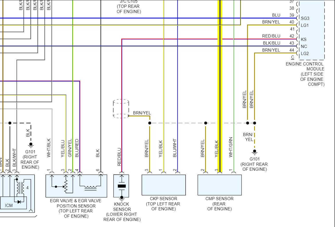
Understanding the Camshaft Position (CMP) Sensor wiring harness is crucial for anyone tackling engine diagnostics, repairs, or performance modifications. A clear understanding allows you to diagnose issues like a misfire, poor fuel economy, or a no-start condition. It also provides a solid foundation for safely and correctly integrating aftermarket components like performance camshafts or standalone engine management systems (ECUs). In this article, we'll delve into the specifics of CMP sensor wiring, from its fundamental purpose to practical troubleshooting techniques.
Purpose of the CMP Sensor Wiring Harness
The CMP sensor harness acts as the vital communication pathway between the CMP sensor and the vehicle's Engine Control Unit (ECU), also sometimes referred to as the Powertrain Control Module (PCM). The CMP sensor detects the position of the camshaft, which directly correlates to the position of the engine's valves. This information, transmitted through the wiring harness, allows the ECU to precisely time fuel injection and ignition events. Without a functioning CMP sensor and wiring harness, the engine won't know when to fire each cylinder, resulting in significant performance problems or complete engine failure.
Think of it like this: the CMP sensor is the engine's eyes, the wiring harness is the optic nerve, and the ECU is the brain. If any part of that system fails, the engine's "brain" cannot properly coordinate its functions.
Key Specifications and Main Parts
A typical CMP sensor wiring harness is relatively simple, usually consisting of just three wires. Let's break down the common components:
Components:
- CMP Sensor Connector: This connects directly to the CMP sensor itself. It's designed to be a secure, weatherproof connection.
- Wiring: Typically 18-22 gauge wire, chosen for its flexibility and current-carrying capacity. Automotive-grade wiring is designed to withstand harsh engine bay conditions: high temperatures, vibration, and exposure to fluids.
- ECU Connector: This connector plugs into the ECU. It provides the electrical interface for the CMP sensor signal to be received and interpreted by the ECU.
- Protective Loom/Conduit: This encases the wiring, shielding it from physical damage, heat, and abrasion. Common materials include corrugated plastic tubing or heat-resistant woven fabric.
Typical Wire Colors & Functions:
Note: Wire colors can vary depending on the vehicle manufacturer. Always refer to the specific wiring diagram for your vehicle.
- Power (Voltage Reference): Typically 5V or 12V supplied by the ECU. Often Red or a similar color.
- Ground: Provides a return path for the electrical circuit. Often Black or Brown.
- Signal: Carries the signal from the CMP sensor back to the ECU. This wire's color is more variable, but often White, Yellow, or Green.
Understanding Wiring Diagram Symbols
Decoding wiring diagrams can seem daunting, but understanding the basic symbols is key. Here's a breakdown of common elements:
- Solid Lines: Represent wires. Thicker lines might indicate higher current-carrying capacity.
- Dashed Lines: Often indicate shielded wiring or a connection within a multi-wire cable.
- Colors: Indicated by abbreviations or color codes next to the wire lines (e.g., "Red" or "RD", "Black" or "BK").
- Connectors: Represented by squares, circles, or specialized symbols indicating the type of connector (e.g., weatherpack, Metri-Pack). Pins within the connector are often numbered or lettered.
- Ground Symbols: Indicate the point where a wire connects to the vehicle's chassis, providing a return path for current. Common symbols include stacked lines or a triangle pointing downwards.
- Component Symbols: Represent the CMP sensor, ECU, and other relevant components. These symbols will vary depending on the diagram's style.
How It Works: The CMP Sensor System
The CMP sensor, typically a Hall-effect or variable reluctance sensor, generates a signal based on the position of a rotating toothed wheel or reluctor ring attached to the camshaft. As the camshaft rotates, the teeth pass by the sensor.
- Hall-Effect Sensor: A Hall-effect sensor contains a semiconductor that generates a voltage when exposed to a magnetic field. As a tooth passes, it interrupts the magnetic field, causing a change in voltage that the ECU interprets as a specific camshaft position. This requires power (typically 5V) to operate.
- Variable Reluctance (VR) Sensor: A VR sensor generates a voltage signal based on the changing magnetic field caused by the passing teeth. It doesn't require an external power source; it generates its own signal.
This signal, transmitted through the wiring harness, allows the ECU to determine:
- Engine Speed (RPM): The frequency of the signal is directly proportional to engine speed.
- Camshaft Position: The ECU uses this information, often in conjunction with the crankshaft position sensor (CKP), to determine the precise position of the camshaft relative to the crankshaft.
The ECU then uses this data to optimize ignition timing, fuel injection timing, and other engine parameters. Without a clean and accurate signal from the CMP sensor through the wiring harness, the engine will likely run poorly, or not at all.
Real-World Use: Basic Troubleshooting
If you suspect a problem with your CMP sensor wiring harness, here are some basic troubleshooting steps:
- Visual Inspection: Carefully inspect the wiring harness for any signs of damage, such as frayed wires, cracked insulation, or corroded connectors. Pay close attention to areas near the engine block or exhaust manifold, where heat exposure is highest.
- Connector Check: Ensure that the connectors at both the CMP sensor and the ECU are securely connected and free of corrosion. Use electrical contact cleaner to clean the connectors if necessary.
- Continuity Test: Use a multimeter to check the continuity of each wire in the harness. Disconnect the harness from both the CMP sensor and the ECU. Set the multimeter to the continuity setting (usually indicated by a diode symbol or a buzzer). Place one probe on one end of the wire and the other probe on the corresponding pin at the other end. A good reading indicates that the wire is intact.
- Voltage Test: With the ignition on (but engine off), use a multimeter to check for the correct voltage at the power wire of the CMP sensor connector (typically 5V or 12V, depending on the vehicle). Refer to your vehicle's wiring diagram for the correct voltage.
- Signal Wire Test: This is trickier and may require an oscilloscope. With the engine running, you can use an oscilloscope to observe the signal from the CMP sensor on the signal wire. A properly functioning sensor will produce a distinct waveform. A multimeter can also be used, but the rapid fluctuation in voltage will be difficult to interpret.
Note: Diagnostic Trouble Codes (DTCs) related to the CMP sensor, such as P0340, P0341, etc., can provide valuable clues to the nature of the problem. Use an OBD-II scanner to retrieve and interpret these codes.
Safety Precautions
Working with automotive electrical systems can be hazardous. Here are some important safety precautions:
- Disconnect the Battery: Before working on any electrical component, disconnect the negative terminal of the battery to prevent accidental shorts and electrical shocks.
- Work in a Well-Ventilated Area: When using electrical contact cleaner or other chemicals, work in a well-ventilated area to avoid inhaling harmful fumes.
- Wear Safety Glasses: Protect your eyes from debris and chemicals.
- Use Proper Tools: Use insulated tools designed for automotive electrical work.
- Be Careful with High Voltage: Be extremely cautious when working near the ignition system, as it can generate high voltages that can be dangerous.
Important: The ECU and some sensors are sensitive to static electricity. Ground yourself by touching a metal part of the vehicle before handling these components.
We've Got Your Diagram Ready
Armed with this knowledge, you're well-equipped to understand and troubleshoot your CMP sensor wiring harness. To further assist you, we have a comprehensive wiring diagram available for download. This diagram provides a detailed visual representation of the CMP sensor circuit, including wire colors, connector locations, and component symbols. This resource will undoubtedly prove invaluable when performing diagnostics and repairs. You can download the diagram here.
Remember to always consult your vehicle's specific service manual for accurate wiring diagrams and diagnostic procedures. Proper diagnosis and repair are crucial for maintaining your vehicle's performance and reliability.