
Can-am Starter Solenoid Wiring Diagram
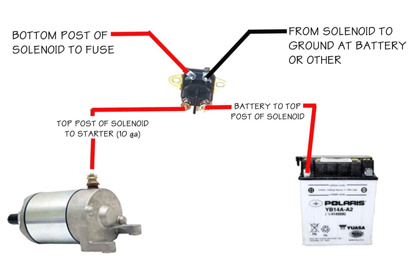
Alright, let's dive into the Can-Am starter solenoid wiring diagram. This document is crucial for anyone tinkering with their Can-Am's electrical system, whether you're performing routine maintenance, troubleshooting a starting issue, adding aftermarket accessories, or simply trying to understand how your machine works. Without a clear understanding of this diagram, you're essentially working blind, and that can lead to costly mistakes or even dangerous situations.
Purpose of the Wiring Diagram
The starter solenoid wiring diagram is your roadmap to understanding the electrical circuitry involved in starting your Can-Am. Its primary purposes are:
- Troubleshooting: Identifying faults in the starting circuit, such as a bad solenoid, wiring issues, or a faulty starter motor.
- Repair: Accurately repairing or replacing damaged components.
- Modification: Safely adding aftermarket accessories that rely on the starting system, like auxiliary lights or winches.
- Understanding: Gaining a deeper understanding of your vehicle's electrical system and how it functions.
Think of it as the electrical equivalent of a mechanical blueprint. It allows you to trace circuits, identify components, and understand the flow of electricity, all without having to physically tear apart your Can-Am.
Key Specs and Main Parts
Before we dissect the diagram, let's familiarize ourselves with the key components you'll encounter:
- Battery: The power source for the entire electrical system. Typically a 12V lead-acid battery in Can-Am models.
- Starter Solenoid: An electromagnetic switch that connects the battery directly to the starter motor. It requires a small current from the ignition switch to activate, which then allows a large current to flow to the starter. This is crucial because the ignition switch isn't designed to handle the high amperage needed to crank the engine.
- Starter Motor: The electric motor that cranks the engine to initiate combustion. It requires a significant amount of current.
- Ignition Switch: The key-operated switch that controls the flow of power to various circuits, including the starter solenoid.
- Fuses: Safety devices that protect the electrical system from overcurrents. The starter solenoid circuit will have its own fuse.
- Ground Connections: Points where the electrical circuit is connected to the vehicle's chassis, providing a return path for the current. A good ground is critical for proper operation.
Common Specifications:
- Voltage: Typically 12V DC.
- Solenoid Current Rating: The maximum amperage the solenoid can handle without damage. This varies by model, but is usually sufficient for the stock starter motor.
- Wire Gauge: The thickness of the wires, specified in AWG (American Wire Gauge). Larger gauge numbers indicate thinner wires. The starter circuit uses thicker wires (e.g., 4 AWG or larger) to handle the high current draw.
Understanding the Symbols
Wiring diagrams use standardized symbols to represent electrical components and connections. Here's a breakdown of the most common symbols you'll encounter in a Can-Am starter solenoid wiring diagram:
- Solid Lines: Represent wires connecting components. The thickness of the line might indicate the wire gauge (thicker lines often denote thicker wires).
- Dashed Lines: Often indicate connections that are grounded to the chassis or body of the vehicle.
- Circles: Can represent various components like lights or sensors, but in the starter circuit, they are unlikely to be used, other than representing connections or junctions.
- Rectangles: Commonly used for relays, switches, and control modules. The starter solenoid is usually represented as a rectangle with connections for the battery, starter motor, and activation circuit.
- Zigzag Line: Typically represents a resistor or a fuse.
- Ground Symbol (Usually three horizontal lines decreasing in length): Indicates a connection to the vehicle's chassis or ground.
Color Coding:
Wire colors are crucial for identifying specific circuits. Common color codes include:
- Red: Usually indicates a positive (+) connection, often directly from the battery.
- Black: Usually indicates a ground (-) connection.
- Yellow: Can be used for various circuits, often related to lighting or signaling.
- Green: Often used for ground connections or sensors.
- Blue: Can be used for various circuits, sometimes related to ignition.
Important Note: Wire color codes can vary slightly between Can-Am models and years. Always refer to the specific wiring diagram for your vehicle.
How It Works
The starting circuit works in a relatively straightforward manner:
- When you turn the ignition key to the "Start" position, a small current flows from the battery, through the ignition switch, and to the starter solenoid's activation circuit.
- This small current energizes the solenoid's internal electromagnet.
- The electromagnet pulls a metal plunger inside the solenoid, connecting the battery's positive terminal directly to the starter motor.
- The starter motor receives a large surge of current, causing it to spin and engage with the engine's flywheel, cranking the engine.
- Once the engine starts and you release the key, the current to the solenoid is cut off, the electromagnet de-energizes, and the plunger disconnects the starter motor from the battery.
The solenoid acts as an intermediary, allowing the low-current ignition switch to control the high-current starter motor. Without it, the ignition switch would quickly burn out due to the high amperage required by the starter.
Real-World Use: Basic Troubleshooting Tips
Here are some common troubleshooting scenarios you might encounter and how the wiring diagram can help:
- Engine Won't Crank:
First, check the battery voltage. If it's low, charge or replace the battery. If the battery is good, use a multimeter to check for voltage at the starter solenoid's activation terminal when the ignition key is in the "Start" position. If there's no voltage, the problem lies upstream, potentially in the ignition switch or wiring. If there is voltage, the solenoid itself might be faulty. You can test the solenoid by jumping the two large terminals together with a heavy-gauge screwdriver (use caution!). If the starter cranks, the solenoid is bad and needs to be replaced. If it still doesn’t crank, the starter motor could be the issue.
- Clicking Sound from Solenoid:
This usually indicates a weak battery or a corroded connection. Clean the battery terminals and check the ground connections. If the problem persists, the solenoid might be failing and not providing sufficient contact to send power to the starter. A drop test with a multimeter across the solenoid terminals when trying to start the vehicle can help to confirm.
- Blown Fuse:
Repeatedly blown fuses in the starter circuit indicate a short circuit somewhere. Inspect the wiring for any signs of damage or chafing that could be causing a short to ground. Use the wiring diagram to trace the circuit and identify potential problem areas.
Safety
Working with electrical systems can be dangerous. Keep these points in mind:
- Disconnect the Battery: Always disconnect the negative battery terminal before working on any electrical component. This prevents accidental shorts and potential shocks.
- High Current: The starter circuit carries a very high current. Be extremely careful when testing the solenoid or starter motor. Accidental shorts can cause severe burns or damage to components.
- Proper Tools: Use insulated tools designed for electrical work.
- Avoid Water: Never work on electrical systems in wet conditions.
- Battery Acid: Batteries contain corrosive acid. Wear eye protection and gloves when handling batteries.
The most risky component in the starting system is the starter solenoid itself. It carries very high amperage, and accidental shorts across its terminals can cause sparks, burns, and even fires. Always use extreme caution when working around it.
With a solid understanding of the Can-Am starter solenoid wiring diagram, you can confidently diagnose and repair starting issues, add accessories, and maintain your machine's electrical system. Remember to always prioritize safety and double-check your work.
We have the file for the Can-Am Starter Solenoid Wiring Diagram for specific models and years, you can download them by visiting the support page.