
Car Air Conditioner Components Diagram
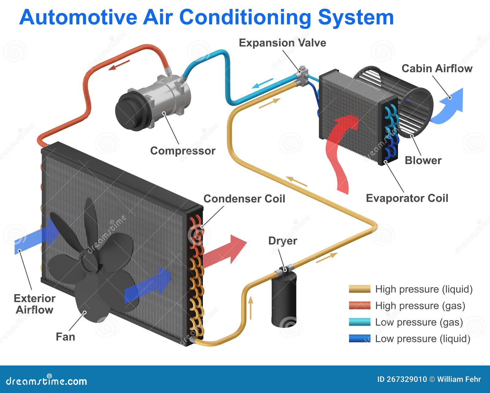
If you're diving into the world of automotive air conditioning, understanding the system's components and how they interact is crucial. A car air conditioner components diagram is your roadmap to diagnosing problems, performing repairs, and even making performance modifications. This article will break down the key elements of the diagram, explain how the system works, and provide some troubleshooting tips to get you started. We even have a downloadable diagram available for your use!
Why This Diagram Matters
Think of an A/C system diagram as the blueprint of your car's cooling system. It allows you to:
- Diagnose Problems: Trace issues like leaks, compressor failures, or refrigerant blockages by pinpointing specific components.
- Perform Repairs: Understand the location and connections of parts for accurate removal and replacement.
- Learn the System: Gain a deeper understanding of how each component functions within the overall A/C system.
- Plan Modifications: For modders and enthusiasts, this diagram can help in planning upgrades or custom A/C installations.
Key Specs and Main Parts
A typical car A/C system consists of several key components, each with a specific role in the cooling process. Here's a breakdown:
- Compressor: The heart of the system, the compressor compresses the refrigerant gas, increasing its temperature and pressure. It's driven by the engine via a belt. Different types exist, including piston, rotary, and scroll compressors.
- Condenser: Located at the front of the car (usually near the radiator), the condenser dissipates heat from the high-pressure, hot refrigerant gas, turning it into a high-pressure liquid.
- Receiver Drier (or Accumulator): This component filters debris, absorbs moisture, and stores refrigerant. The receiver drier is typically found in systems using a thermal expansion valve (TXV), while an accumulator is used with orifice tube systems.
- Expansion Valve (or Orifice Tube): This component reduces the pressure of the liquid refrigerant before it enters the evaporator. The TXV is a more sophisticated valve that regulates refrigerant flow based on evaporator temperature, while the orifice tube is a fixed-size restrictor.
- Evaporator: Located inside the car's dashboard, the evaporator absorbs heat from the cabin air, causing the liquid refrigerant to evaporate into a low-pressure gas, thereby cooling the air blowing into the cabin.
- Refrigerant Lines: These hoses and pipes transport the refrigerant between components. They are typically made of rubber or aluminum and are designed to withstand high pressures.
- Pressure Switches: These switches monitor the refrigerant pressure and protect the system from damage. They can shut down the compressor if the pressure is too high or too low.
- Blower Motor: This motor forces air across the evaporator core to distribute the cooled air into the cabin.
- Control System: This includes the dashboard controls, sensors, and electronic control unit (ECU) that regulate the A/C system's operation.
Symbols: Lines, Colors, and Icons
A/C system diagrams use standard symbols to represent components and their connections. Here's a guide to understanding common symbols:
- Lines: Solid lines usually represent refrigerant lines, while dashed lines might indicate electrical connections or control lines. The thickness of the line can sometimes indicate the size of the refrigerant line.
- Colors: Color-coding can vary between diagrams, but common conventions include:
- Red: High-pressure refrigerant lines.
- Blue: Low-pressure refrigerant lines.
- Green: Electrical ground.
- Yellow: Electrical power.
- Icons: Each component has a specific icon. For example:
- Compressor: Often depicted as a circle with a piston or spiral inside.
- Condenser: A series of zig-zag lines representing the cooling fins.
- Expansion Valve: A diamond shape with an arrow indicating the direction of flow.
- Evaporator: Similar to the condenser, but usually smaller.
- Flow Direction: Arrows indicate the direction of refrigerant flow within the system.
Always refer to the diagram's legend or key for specific symbol definitions, as they can vary between manufacturers and models.
How It Works
The A/C system operates on a closed-loop cycle:
- Compression: The compressor increases the pressure and temperature of the refrigerant gas.
- Condensation: The high-pressure, hot refrigerant gas flows to the condenser, where it cools and turns into a high-pressure liquid.
- Metering: The high-pressure liquid refrigerant passes through the expansion valve or orifice tube, which reduces its pressure and temperature.
- Evaporation: The low-pressure, cold refrigerant flows into the evaporator, where it absorbs heat from the cabin air and evaporates into a low-pressure gas.
- Return: The low-pressure refrigerant gas returns to the compressor to begin the cycle again.
Throughout this cycle, the refrigerant changes state from gas to liquid and back again, absorbing and releasing heat to cool the car's interior.
Real-World Use: Basic Troubleshooting Tips
Using the A/C components diagram can help you diagnose common issues:
- No Cold Air: Check the compressor clutch for engagement. If it's not engaging, check the pressure switches and electrical connections. A refrigerant leak could also cause low pressure, preventing the compressor from engaging.
- Weak Airflow: Inspect the blower motor and its resistor. Also, check for obstructions in the air ducts or a clogged cabin air filter.
- Cycling On and Off: This could indicate low refrigerant levels or a malfunctioning pressure switch. Use gauges to check the refrigerant pressure.
- Strange Noises: Noises from the compressor could indicate internal damage. Hissing sounds might indicate a refrigerant leak.
Remember to use proper diagnostic tools, such as manifold gauges and leak detectors, for accurate troubleshooting.
Safety
Working with A/C systems involves handling refrigerants under high pressure and electrical components. Always observe these safety precautions:
- Refrigerant: Refrigerants can cause frostbite and asphyxiation. Wear appropriate personal protective equipment (PPE), such as gloves and safety glasses. Never vent refrigerant into the atmosphere, as it's harmful to the environment. Recover and recycle refrigerant properly.
- High Pressure: Be extremely careful when working with pressurized lines. Use proper tools and techniques to avoid rupturing hoses or fittings.
- Electrical: Disconnect the battery before working on any electrical components of the A/C system. Be aware of high-voltage components, such as the compressor clutch wiring.
- Compressor Oil: Be aware that some refrigerant lines contain compressor oil which can be messy and slippery. Clean up any spills immediately.
Always consult a qualified technician if you are unsure about any aspect of A/C system repair.
With a solid understanding of the A/C system components diagram and the underlying principles of operation, you'll be well-equipped to tackle basic diagnostics and repairs on your car's air conditioning system. Remember safety first and when in doubt, consult a professional.
We have the detailed A/C components diagram file ready for you. You can download it [link to download here]. Use it as your go-to reference guide as you delve deeper into automotive A/C systems!