
Car Air Conditioner Electrical Diagram
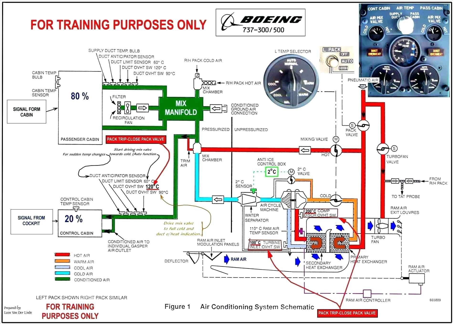
So, you're looking to understand your car's air conditioning electrical system. Smart move! The AC system is often a source of mystery, but with a little understanding of the electrical diagram, you can diagnose problems, perform repairs, or even make informed modifications. This guide will break down the schematic, explain the key components, and give you the knowledge to confidently tackle your AC system.
Purpose of the AC Electrical Diagram
Why bother understanding the electrical diagram? Several reasons:
- Troubleshooting: When your AC isn't working, the diagram helps you trace the electrical path, identifying faulty components like relays, switches, or wiring issues. Instead of blindly replacing parts, you can pinpoint the exact cause.
- Repairing: After identifying a bad part, the diagram shows you where it's located in the circuit and how to replace it.
- Modifying: Want to add a custom switch or upgrade a component? The diagram provides the essential information for safe and effective modifications.
- Understanding: Simply knowing how the system *should* work helps you understand *why* it's failing. Knowledge is power!
In essence, the electrical diagram is the roadmap to your car's AC system. Without it, you're driving blind.
Key Specifications and Main Parts
Before diving into the diagram itself, let's review the main components typically found in a car's AC electrical circuit. These components will almost always be present, though their specific implementation may vary by vehicle make and model.
- Battery: The source of electrical power (typically 12V DC).
- Fuse/Circuit Breaker: Protects the circuit from overloads. A blown fuse is often the first sign of a problem.
- Ignition Switch: Controls power to various circuits when the key is turned.
- AC Switch: Activates the AC system when pressed.
- Blower Motor Switch: Controls the speed of the blower motor (low, medium, high). This is often integrated with the AC switch.
- Blower Motor: Provides airflow through the evaporator core.
- Compressor Clutch Relay: A relay controlled by the AC switch and other sensors that engages the AC compressor.
- AC Compressor: Compresses the refrigerant, which is the heart of the AC system.
- Pressure Switch(es): These are safety devices that prevent the compressor from running if the refrigerant pressure is too low or too high. There are typically *low-pressure* and *high-pressure* cut-off switches.
- Thermostat/Temperature Sensor: Monitors the evaporator core temperature to prevent freezing.
- Engine Control Unit (ECU)/Powertrain Control Module (PCM): In modern vehicles, the ECU/PCM often plays a role in managing the AC system, particularly the compressor operation.
- Wiring Harness: The collection of wires that connects all the components.
- Ground Points: Points where the circuit completes back to the vehicle chassis, providing a return path for the current.
Key Specs: You will want to know the voltage (usually 12V DC) and the amperage ratings of the fuses. These will be listed in the vehicle's service manual or on the fuse box cover. Knowing the wiring gauge (thickness) is also important, especially if you're modifying the system. Thicker wires can carry more current.
Decoding the Symbols
The electrical diagram uses a standardized set of symbols to represent each component. Learning these symbols is crucial for understanding the schematic.
- Lines: Solid lines represent wires. Dashed lines sometimes indicate shielding or communication lines. The thickness of the line generally doesn't represent wire gauge.
- Colors: Wires are often color-coded (e.g., red for power, black for ground). The diagram will typically include a color code legend. Pay close attention to the legend; color codes can vary by manufacturer.
- Battery: Represented by a series of short and long parallel lines.
- Fuse: Represented by a zigzag line inside a rectangle.
- Switch: Represented by a line that can connect or disconnect two points. Different switch types (SPST, SPDT, DPDT) have different symbols.
- Relay: A coil represents the relay's electromagnetic coil, and a switch represents the contacts that the relay controls.
- Motor: Represented by a circle with an "M" inside.
- Ground: Represented by a series of lines decreasing in length, connected to a single point.
- Resistor: Represented by a jagged line.
- Diode: Represented by a triangle pointing to a line.
- Capacitor: Represented by two parallel lines.
Understanding these basic symbols will allow you to trace the flow of electricity through the circuit.
How It Works: The Electrical Flow
The typical AC electrical circuit works like this:
- Power flows from the battery, through a fuse (for protection), and to the ignition switch.
- When the ignition switch is turned on, power is supplied to the AC switch.
- When the AC switch is pressed, it sends a signal to the ECU/PCM (in modern vehicles) and/or directly to the compressor clutch relay.
- The ECU/PCM may check various sensors (e.g., engine temperature, vehicle speed) before allowing the AC compressor to engage.
- The pressure switch(es) are in series with the compressor clutch relay coil. If the refrigerant pressure is too low or too high, the switch opens, cutting off power to the relay.
- The compressor clutch relay, when energized, closes a high-current circuit that supplies power to the AC compressor clutch.
- The AC compressor clutch engages, driving the compressor.
- The blower motor receives power through the blower motor switch, allowing the driver to control the airflow.
- The thermostat/temperature sensor monitors the evaporator core temperature and can disengage the compressor if the core is in danger of freezing.
This is a simplified overview, and the specific details can vary. For example, some vehicles have a separate AC amplifier that controls the compressor. The diagram will show you the exact flow of electricity in your specific vehicle.
Real-World Use: Basic Troubleshooting Tips
Here are some common AC electrical problems and how to use the diagram to troubleshoot them:
- AC Not Working at All:
- Check the AC fuse. If it's blown, replace it. If it blows again immediately, there's a short circuit somewhere. Use the diagram to trace the wiring and look for damaged insulation or pinched wires.
- Check the compressor clutch relay. You can test it by swapping it with a known good relay (e.g., the horn relay).
- Check the pressure switch(es). You can use a multimeter to check for continuity.
- AC Works Intermittently:
- Could be a loose connection. Check all connectors in the AC circuit.
- Could be a faulty relay that's overheating.
- Blower Motor Not Working:
- Check the blower motor fuse.
- Check the blower motor resistor pack (often fails).
- Check the blower motor itself.
Important: Always disconnect the battery before working on any electrical system to prevent shorts and potential injury.
Safety: Highlighting Risky Components
The AC electrical system can be dangerous if not handled properly.
- High Voltage/Current: The AC compressor clutch circuit can draw significant current. Always disconnect the battery before working on this circuit.
- Sharp Objects: Be careful when working around the evaporator core and condenser. They have sharp fins.
- Refrigerant: While this article focuses on the electrical aspects, remember that refrigerant is a dangerous chemical. If you suspect a refrigerant leak, have it serviced by a qualified technician.
Always prioritize safety. If you're unsure about any step, consult a professional.
Understanding your car's AC electrical diagram is a powerful tool for diagnosing and repairing AC problems. With a little patience and the right information, you can save money and keep your car cool and comfortable.
We have a generic AC electrical diagram available for download. This diagram provides a basic overview of the AC electrical system and can be a helpful reference tool. However, remember that your vehicle's specific wiring may differ. Always consult the service manual for your specific make and model for accurate information.
I hope this information helps you better understand your car's AC electrical system and equips you with the knowledge to tackle any future AC challenges. Good luck!